In this tutorial, I will measure DC current using the Acs712 Hall effect-based linear current sensor and the Arduino Uno. The Acs712 can measure current precisely and accurately if managed correctly. I read several blogs on the internet about interfacing the acs712 current sensor with Arduino and other microcontrollers. I discovered that they are all measuring current with formulas (derived from the acs712 current sensor) that are not accurate. So, I decided to write a tutorial about the acs712 current sensor and present a practical example with circuit and code. In this tutorial, I will define the best method and precise formula generation to measure DC current with the acs712 current sensor. I will define each step of the code and circuit completely and deeply with logic. The project code is open source and you can download and modify it according to your needs.
The Acs712 current sensor can measure direct and alternating current. For this post/tutorial/project I will only measure DC current. The formula derived and explained in the tutorial is for direct current measurement only. You cannot use the formula below to measure alternating current with the acs712 Hall effect current sensor.
The Acs712 current sensor can measure direct and alternating current. For this post/tutorial/project I will only measure DC current. The formula derived and explained in the tutorial is for direct current measurement only. You cannot use the formula below to measure alternating current with the acs712 Hall effect current sensor.
About Acs712
ACS712 is a Hall effect-based linear current sensor that can measure DC (direct current) and AC (alternating current). The sensor chip is manufactured by Allegro www.allegromicro.com. The pinout and pin description of the chip are below.
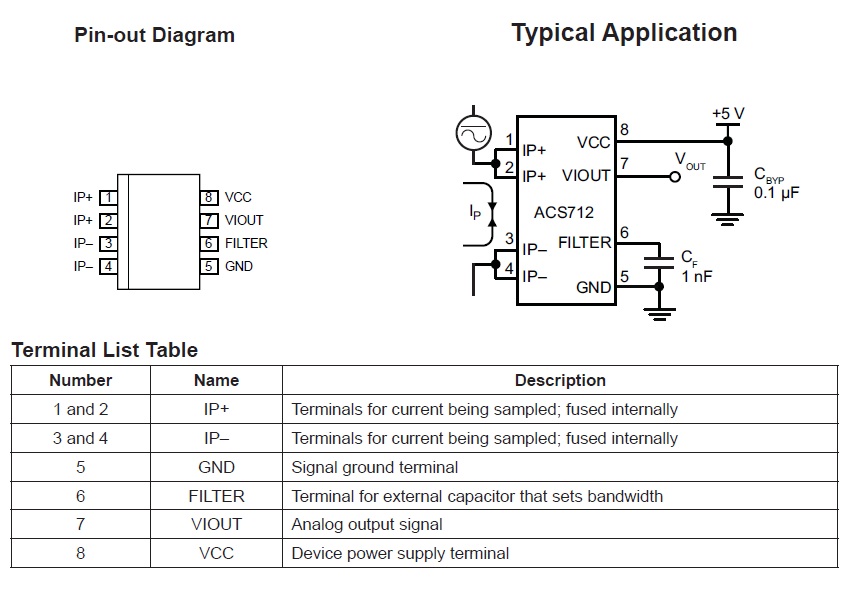
IP+ and IP-
VIout
Viout is the voltage output pin. The ACS712 outputs an analog signal that corresponds to any variation between the IP+ and IP- pins or, in other words, outputs analog voltage at the VIOUT pin if there is any variation in current.
Quiescent output voltage (VIOUT(Q)). The device output when the primary current is zero. For a unipolar supply voltage, it nominally remains at VCC⁄2. Thus, VCC = 5 V translates to VIOUT(Q) = 2.5 V. The variation in VIOUT(Q) can be attributed to the resolution of Acs712. If the Acs712 is running at 5v (Vcc = 5v) and there is no current flowing from the input, the output will be 2.5v . 2.5V is the base voltage at 5V input, now any change in input current will bring change in output voltage . Viout decreases when current starts flowing through the ACS712 pins.
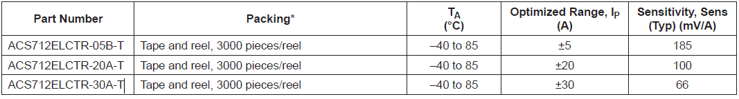
Acs712 is commercially available in three classifications.
- ACS712ELCTR-05B-T
- ACS712ELCTR-20A-T
- ACS712ELCTR-30A-T