How to detect variations in EEG signals in the form of LEDs using LM3915
SOMA MARY
After taking over the relay device control experiment, I'm thinking about analyzing the EEG wave produced by the brain and seeing the variations in the shape of the LEDs. It would be really nice if we could clearly see the variations of our EEG signals in the form of some LED patterns, so as to analyze how much variation is being produced by various thought processes. Let's start.

Fig. 1: Image showing EEG signals displayed as changing LED light
DESCRIPTION
I decided to use IC LM3915 which can convert analog voltage into digitized form from 1 to 10 and rotate as many LEDs as the digitized value. It can also be called ADC (Analog to Digital Converter). When analyzing our CR wave, we saw that the voltage range is up to 1V. So we set the LM3915 reference to 1V. By doing this, we transmit to the LM3915 that 0v means 0 LEDs and 1V means 10 LEDS. So now let's say 4 LEDs are glowing, that means the voltage is close to 0.4 V. We just send the analog EEG signal directly to the IC LM3915 and connect LEDs at the other end to get the result. Please watch the experiment video.

Fig. 2; Image showing EEG signals displayed as changing LED light
We can conclude that the waves are not very stable in magnitude. I also believe there will be some noise that has been transferred to the 3915 IC. This can also be seen that often the LEDs go to full magnitude and stay there, which is not the case when checked with CRO. This could be due to noise as we just soldered the wire and it is open and long too. Anyway, brain waves are very interesting and I'm still trying to find some patterns in them to carry out more experiments of this type. By this experiment, I discovered the variation in our EEG and the effect of noise. I'm assuming this as noise, but it could be something else.

Figure 3: Block diagram of EEG signal LED indicator based on MindFlex brainwave sensor
Hardware: Please find the attached circuit diagram of the connections that must be established. We solder a pin to the EEG pin of the Mindflex sensor and insert the output of the EEG pin into the input of the LM3915. Additionally, we also set the reference voltage to 1V as our EEG signals will not exceed this value. To set 1V, we are using the resistor network. Although we can use 10 LEDs with the 3915IC, here we will only use 4 LEDs just to see the variations and changes of our EEG wave.
Project source code
###
//Program to/*
###
Circuit diagrams
| Circuit-Diagram-MindFlex-Brainwave-Sensor-EEG-Signal-LED-Indicator | 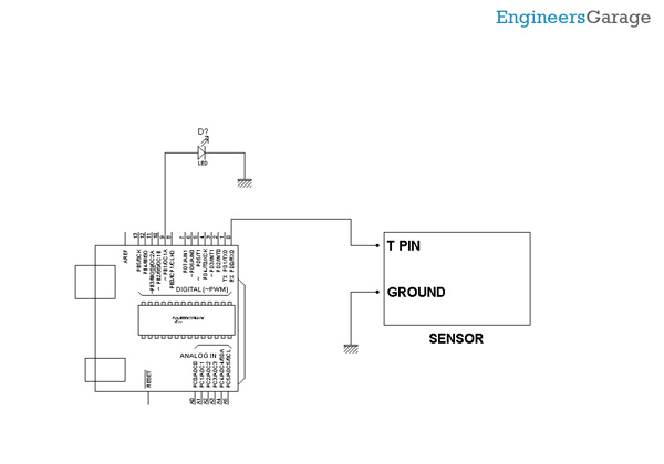 |