In the previous tutorial , we learned how to interface a seven-segment display with Arduino. A seven-segment display is made up of a unit of eight LEDs, seven of which are bar-shaped and one of which is a dot. These display units are ideal for displaying numbers or letters.
For example, they are often used as a display unit in cost-sensitive applications where an embedded system may only require numerical information, such as a digital clock or token display board. This option is typically more cost-effective than full LCD monitors.
In the previous tutorial, we discovered that interfacing a single seven-segment display requires eight or nine connections. The seven-segment unit can only display a single digit. If more digits are needed, more segments are needed.
If each seven segments are independently interfaced with the controller (such as Arduino ), multiple digital I/O channels are required. Generally, the number of digital I/O pins on any controller is limited. However, many seven-segment displays can be interfaced to a controller using the multiplexing technique.
By using this technique, the number of pins required to interface multiple seven-segment devices with a controller can be greatly reduced. There are also several seven-segment display driver ICs that can perform the multiplexing technique and use standard serial interfaces to communicate with a controller.
MAX7219 is an LED driver IC that allows multiplexing of up to eight seven-segment displays. It uses an SPI interface to communicate with the controller. This way, only three controller pins are activated to control eight of the seven-segment displays. Otherwise, direct multiplexing would require at least 16 digital I/O pins.
Seven-segment multiplexing
There are two types of seven-segment displays: common cathode and common anode.
When a single seven-segment common cathode interfaces to a controller, the common cathode terminal is usually connected to ground. Likewise, when a single seven-segment common anode is interfaced to a controller, the common anode terminal is typically connected to VCC. This way the seven segments are always active and ready to turn on/off their LEDs according to the logic signal on their data pins (a, b, c, d, e, f, g and dp).
With the multiplexing technique, multiple seven segments are interfaced with a controller and the respective data lines of all segments are shortened. Thus, when the controller transfers the logic to turn on/off the segments, it is passed to all seven segments at the same time. However, only one display unit is activated at a time.
Additionally, each of the seven segments multiplexed with a controller must be of the same type (i.e., they must all be common anode or common cathode).
The common anode or common cathode terminals are not connected to VCC or ground. Instead, they interface with the microcontroller pins. The common anode or common cathode terminals of the seven segments serve as select lines. One of the segments can be selected by passing the relevant logic to the common cathode/common anode terminals.
If it is common anode, seven segments are multiplexed:
- One of the seven segments can be selected by passing a logic HIGH to the common anode terminal which must remain activated at a time.
- All other seven segments can be kept inactive by maintaining a logic LOW at their common anode terminals.
- The desired digit can be displayed on the seven selected segments by turning on the appropriate LED segments by simply passing a logic LOW to the respective data lines.
Similarly, if the common cathode, seven segments are multiplexed:
- One of the seven segments can be selected by passing a logic LOW to the common cathode terminal which must remain activated at a time.
- All other seven segments can be kept inactive by maintaining a logic HIGH at their common cathode terminals.
- The selected digit can be displayed in the seven selected segments by turning on the appropriate LED segments passing a logic HIGH to the respective data lines.
The seven multiplexed segments can be viewed as an array of LEDs grouped by seven-segment display units – each unit activates one after the other. The unit's LEDs are controlled by passing the appropriate logic.
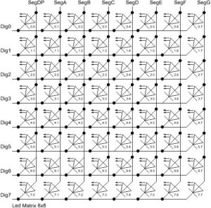
Only one seven segment is activated at a time and the desired digit is displayed on it. Then the other seven segments are activated and the selected digit is displayed in it. This continues for all seven multiplexed segments.
If 25 frames (or more) are displayed in one second, the human eye will see the frames as one continuous display. Thus, the seven multiplexed segments will appear as if they are displaying the digits simultaneously.
LED Driver ICs
Even when seven segments are multiplexed directly onto a controller's digital I/O pins, they involve many pins. Interfacing every seven segments requires the involvement of an additional pin on the controller. Not counting the eight pins already occupied for data lines. If the eight or seven segments are interfaced to the controller, 16 digital I/O pins are required (eight for the data lines and eight for the select lines).
However, not all microcontrollers have so many GPIOs. And even if they do, it's typically not advisable to use that many pins to interface with a display system. This is because other components may also require interfacing with the controller.
The solution to this problem: LED driver ICs. These ICs perform multiplexing on their own channels/pins, meaning the seven LED segments or arrays can be controlled via standard serial interfaces (such as SPI or I2C). LED driver ICs only require obtaining data from the controller, using the I2C interface or a three-wire SPI.
I2C allows half-duplex data communication over two wires. This means that an LED display driver IC using the I2C interface involves just two pins of a microcontroller to control several of the seven-segment displays or the LED matrix.
Three-wire SPI allows unidirectional data communication over three wires. An LED display driver IC using a three-wire SPI involves just three pins of a microcontroller to control several of the seven-segment displays or the LED matrix.
The MAX7219 8-Digit LED Driver
MAX7219/MAX7221 is an eight-digit common cathode LED display driver. Allows interfacing of a microprocessor or microcontroller with seven-segment display units with up to eight digits. 64 LED bar and matrix graphic displays can also be interfaced with a controller/computer using this IC.
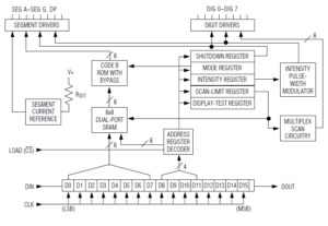
IC includes:
- An on-chip B-code BCD decoder
- A segment and digit driver
- A multiplex scan circuit
- An 8x8 static RAM to store up to eight digits
The IC has a 10 MHz serial interface that can communicate with a controller/computer through an IPS, a QSPI or a MICROWIRE.
It operates from a 5V 330mA supply and consumes only 150 uA of current in off mode. For 3V operation, the MAX6951 can be used. The MAX7219/MAX7221 supports shutdown mode, analog and digital brightness control, and test mode that forces all LEDs to light. Each LED segment can also be controlled individually by this driver.
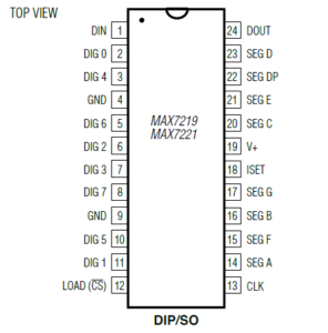
The MAX7219 comes in 24-pin DIP and OS packages, with the following pin diagram:
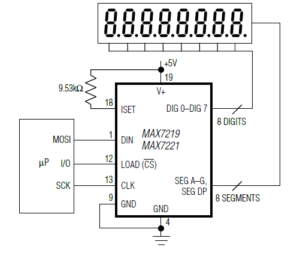
The MAX7219 has this functional diagram:
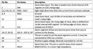
The MAX7219 IC has the following pin configuration:
Multiplexing with Arduino using MAX7219
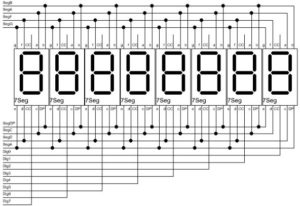
It is quite simple to multiplex the eight and seven segment display units with a controller/computer via the MAX7219/MAX7221.
- The data pins of the seven segments must first be connected to the SEG A to the SEG G and DP pins of the MAX7219.
- The common cathode terminals of the segments must be connected to the DIG0 to DIG7 pins of the MAX7219.
- Pins 4 and 9 of the IC must be connected to ground.
- Pin 19 of the IC must be connected to 5V DC.
- Pin 18 of the MAX7219 must also be connected to 5V DC through a suitable resistor.
- The DIN, LOAD and CLK pins of the IC must be connected to the digital I/O pins of a controller/computer.
An SPI interface with Arduino
The SPI bus is a master-slave synchronous serial data bus. There can only be one master on an SPI bus, and multiple slave devices can share it.
An SPI bus has four wires:
1. Master Out Slave In (MOSI) — for transferring data from master to slave
2. Master In Slave Out (MISO) — for data transfer from slave to master
3. Serial Clock (SCK/SCLK) — for clock signal from master to slave
4. Slave Select (SS on Master)/Chip Select (CS on Slave) — for slave selection by the master
Some electronic components only require the transmission or reception of data. These parts can only have a MISO or MOSI channel. Some devices use a three-wire SPI, in which MISO and MOSI are combined with one wire, and are called MIMO.
An SPI bus can communicate data to hardware through a simple shift register. Data bits are communicated uninterruptedly and continuously with each bit transferred in each clock pulse.
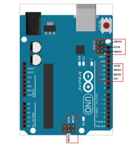
Most Arduino boards have at least one SPI interface. The SPI Interface on the Arduino UNO is shown here:
How the MAX7219 works on the SPI bus
The MAX7219 IC requires a three-wire SPI bus for data communication with a controller/computer, where the bus has only MOMI, CLK and SS/CS pins.
The IC has an internal 16-bit shift register where data is transferred from a controller/computer when there is a rising edge on the LOAD pin of the IC. Data transferred to the IC through an SPI is two bytes long.
- The first byte is the address of an internal register, which selects one of the internal registers.
- The second byte writes data to the selected internal register.
By passing the 16-bit data to the IC, multiple seven-segment digits – and features such as brightness control, test mode, and power-off mode – can be controlled.
The MAX7219 records
The MAX7219 has these internal registers…
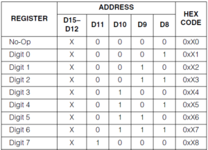
Autonomous Register – When data is transferred to this register, no operations are performed on the seven-segment display units of the supplied MAX7219 IC. This register is used when multiple MAX7219 ICs are connected in series.
For example, if four MAX7219 ICs are connected in series, to transfer data to a fourth IC, the first three MAX7219 ICs must have data written to their non-operational registers. This register has an address bXXXX0000 (0xX0).
DigitRegisters – used to control the eight digits displayed on the seven-segment display units. There are eight-digit registers that have addresses from bXXXX0001 (0xX1) to bXXXX0111 (0xX7).
Decode Mode Register – Selects BCD Code-B or no decode operation for each digit. Each bit in the register corresponds to a digit. A HIGH logic selects decoding of the B code and a LOW logic ignores the decoder. This register has an address bXXXX1001 (0xX9).
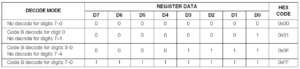
If BCD-B Code is selected for a digit, the decoder only looks at the lower nibble of the data in the digit registers (D3–D0) — disregarding bits D4–D6.
Bit D7 of the digit registers is independent. If set to HIGH, activates the decimal point. Otherwise, if set to LOW, it disables the decimal point.
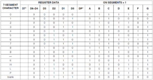
The BCD-B code controls the seven-segment digits according to the following table:
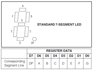
If no decoding is selected, data bits D7–D0 of the digit registers correspond to the segment lines of the MAX7219/MAX7221 as shown here:
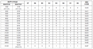
Intensity register – controls the brightness of the segments. It has an address bXXXX1010 (0xXA). If a minimum value resistor (9.53 kΩ) is connected between the V+ and ISET pins, the peak current supplied to the segments will be 100 times the current entering the ISET pin. This current can be controlled digitally by recording data in the intensity register.
The screen brightness is digitally controlled using an internal pulse width modulator, which scales the segment current in 16 steps.
This pulse width modulator is controlled by the lower nibble of the intensity register, as shown in the table:
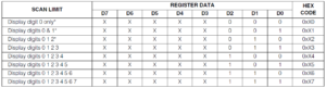
Scan Limit Register – Controls the number of digits displayed by the MAX7219/MAX7221. It has an address bXXXX1011 (0xXB).
The digits to be displayed are controlled according to this table:
Shutdown register – if the LSB of this register is set to 0, the MAX7219/MAX7221 goes into shutdown mode and all digits are turned off. This register has an address bXXXX1100 (0xXC).
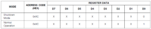
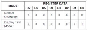
Display Test Register – If the LSB of this register is set to 1, the MAX7219/MAX7221 enters display test mode and all digit segments are activated. This register has an address bXXXX1111 (0xXF).
Controlling the seven segments through the MAX7219
To control the seven-segment multiplexed display units through the MAX7219/MAX7221, the controller/computer must write data to the IC's internal registers using the SPI, QSPI, or Microwire bus.
The data is passed to the IC's internal 16-bit shift register, where the first byte selects an internal register and the second byte writes the data to the selected register. If the seven-segment display units or IC need to be tested, data can be written to display the test register (address byte 0x0F). It will confirm that all seven segment digits are operational.
The display brightness can be controlled by writing data to the intensity register (address byte 0x0A). The number of digits to be used can be implemented by writing data to the scan limit register (address byte 0x0B). Then, the decoding mode must be selected by writing the data to the decoding mode register (address byte 0x09).
The individual digits can then be controlled by writing data to the digit registers (addresses 0x01 to 0x08). If the display needs to be turned off, the MAX7219 can be forced into shutdown mode by writing data to the shutdown register (address byte 0x0C).
If more than one MAX7219/MAX7221 IC is connected in series, the non-operational register (address byte 0x00) can be used during data transfer between the series-connected MAX7219s/MAX7221s.
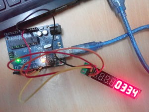
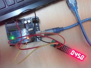
Recipe: Seven-segment display counter using Arduino and MAX7219
In this recipe, we will design a numeric counter using seven-segment display units, a MAX7219 LED driver IC and Arduino UNO. The counter will count from 0000 to 9999.
Required components
1. Arduino UNO x1
2. SSD x4
3. MAX7219 x1
4. Jumper or connecting wires
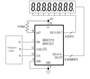
Circuit Connections
A seven-segment driver module based on IC MAX7219 is used. The DIN, CLK and LOAD pins of the IC are connected to pins 12, 11 and 10 of the Arduino UNO respectively. The MAX7219 IC comes with 5V DC and Arduino ground.
Arduino Sketch
How the project works
The seven-segment multiplexed display units interface with the MAX7219 IC. The IC interfaces with the Arduino UNO via the SPI bus. Using Arduino's SPI interface, 16 bits of data are transferred to the shift register of the MAX7219 IC.
When writing data to the IC MAX7219's internal registers, seven-segment digits are controlled to display a counter of numbers 0000 to 9999
Programming guide
The Arduino sketch starts by importing the SPI library. Global variables are defined to assign pin numbers that are connected to DIN, CLK and LOAD pins of IC MAX7219. An array type variable is defined to store the 16-bit commands for the MAX7219.
A character table is stored in the Arduino UNO's flash memory using the PROGMEM construct. This table contains the bytes that must be written to the LED segments to display the digits 0 to 9 and the letters A to F.
A spiTransfer function is defined for the shiftOut function to transfer the 16-bit data to the MAX7219 IC. Each 16-bit data contains two bytes. The first byte is the address of the MAX7219 register and the second byte is the data to be written to a selected register. Both bytes are passed as arguments to this user-defined function.
A clearDisplay function is defined, where the spiTransfer function is used to write 0x00 to all digit registers to clear all digits. A shutdown function is defined, which uses the spiTransfer function to write data to the MAX7219 shutdown mode register.
An init_7seg function is defined to initialize the view. In this function, the MOSI, SCLK and CS pins are configured for digital output. The CS pin is set to HIGH to select the MAX7219 on the SPI bus.
A value of 0x00 is transferred to the display test register (register address 15 or 0x0F) using the spiTransfer function to set the MAX7219 to normal mode. A value 0x07 is transferred to the limit register scan (register address 11 or 0x0B), allowing the use of all eight digits. A value of 0x00 is transferred to the decode mode register (register address 9 or 0x09) to select “no decode” for all digits.
A setChar function is defined that writes a value to the MAX7219's digit register. Both the value and the digit are defined as parameters of the function. In this function, the validation of the passed digit and value data is completed. Then the checked value is passed to a given digit register using the spiTransfer function.
In the setup function, the init_7seg and shutdown(false) functions are called. The spiTransfer(10, 8) function is called to set the display intensity. The display is cleared by calling the clearDisplay function.
In the loop function, a “for loop” is performed for the values 0 to 9999. For each number, four digits are derived using arithmetic operations and the digits are displayed in the seven multiplexed segments using the setChar function. Each number is incremental and displayed at a 250 millisecond interval. The delay is provided via the delay function.
In the next tutorial we will cover how to interface the character LCD with Arduino.