
Changing the color of the RGB LED
SUMMARY
In this series we conducted several experiments, of which the previous one was related to dancing LEDs. Now let's do some more experiments and see how far we can extend the brain wave.
Previously, we changed the LED Brightness using the Attention and Meditation values . The results were good and we were able to perceive the variation in the form of brightness. Although we did not get a very clear variation, we also performed a similar experiment using the motor and changed the motor speed. Now let's try another experiment like this and this time we're going to change the color of the RGB LED . Furthermore, we previously used attention/meditation waves of and meters; this time we will use some brain waves to control the color.

Fig. 1: Image showing RGB LED color change by Brainwave
DESCRIPTION
RGB LEDs are colored LEDs that can change color depending on the input. These LEDs are also controlled by the PWM wave. Many of the things that work in variations can be controlled by PWM. Therefore, in this article we will apply an RGB LED in front of the pin while changing the values.

Fig. 2: Image showing RGB LED color change by Brainwave

Fig. 3: Image showing RGB LED color change by Brainwave

Fig. 4: Image showing RGB LED color change by Brainwave
We will take the signals from the Mindflex Sensor and then extract the values of the desired signal. Once we get the value, we will map the value from 0 to 255. We also looked at PWM calculations earlier.

Fig. 5: Block diagram of RGB color changer based on brainwave module
Hardware: Find the attached circuit diagram of the connections that need to be established. We take a pin from the T pin of the mindflex sensor and connect this pin to the Rx pin of our Arduino UNO. Additionally, we short-circuited the Sensor and UNO ground by a wire. Take special care when soldering anything to the Mindflex sensor, as the pins are very close to each other. After that, an LED is connected to PIN 9, through which PWM signals are sent.
Programs: Let's go to the software part. We have been receiving the E meter values from the sensor to our arduino via T pin. Once we receive the value at any specific point, we just need to convert that value level to the LED brightness. As discussed earlier, we will use PWM techniques. PWM on Arduino is done by analogWrite.
For example:
AnalogWrite(13,240);
AnalogWrite in Arduino is used to write PWM wave to a pin. In the example above, the first parameter is the PIN number and the second is the PIN value. So we are writing 240 on pin 13. Now we can easily calculate the analog voltage at value 240. The total voltage range is 0V to 5V and the range of values is 0 to 255.
This means 240 = (5/255)*240 = ~4.70V.
The values we obtain for and meters are in the range from 0 to 100.
So let's say we have evalue = 70.
We will multiply the value of e by 2.55 to put it in the range 0 to 255.
It will be analogWrite(pin,evalue*2.55) in a loop.
Now the values we are getting are in the range of 0 to 999999, so we will map the values in the range of 0 to 255 to produce the above results, using the arduino's map function.
output = map(num,0.999999,0.180);
Some points to note:
The sensor usually provides 60 to 80% resistance due to its orientation and the location where we place it. Try to keep the metal sensor exactly above your left eye. I also applied salt water to my forehead for better connectivity with the sensor. If you don't find 100%, then it's normal.
The signal strength also messes with how we solder the wire to the T pin. Try shielding this wire and also make sure the reference probes are connected correctly. If you have any wires connected to the sensor's EEG pin, disconnect that wire as this can create a lot of noise in the sensor values.
You can also try this experiment on your own and let us know about your valuable feedback. Stay tuned for our next experiment on controlling servo motor through brain waves.
Project source code
###
//Program to#include
###
Circuit diagrams
| Circuit-Diagram-Brain-Wave-Module-RGB-Color-Changer | 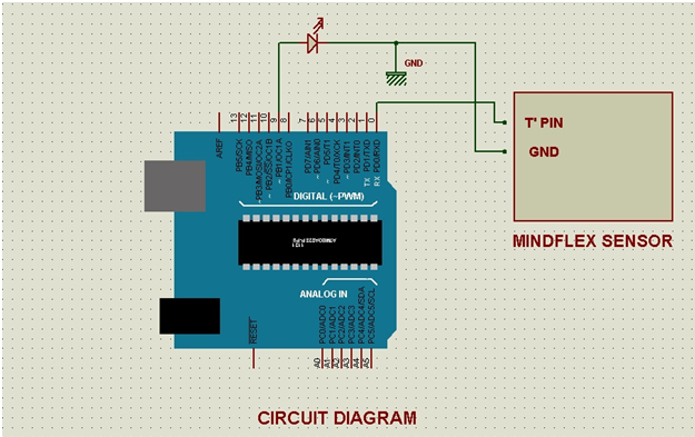 |


