As an example, let's consider a typical helical cylindrical gear. Using a four-axis machining center and CAXA software, we will explore the four-axis NC machining method of helical gears through cutting simulation verification and actual cutting on the machine tool using VERICUT.
1. Preamble
The processing of spur and helical cylindrical gears is typically achieved through milling, gear shaping or gear grinding. With the advancement of the four-axis machining center, processes that were previously challenging to complete on three-axis machining centers can now be performed on four-axis equipment. In this article, we will examine the four-axis NC machining method of a typical helical gear.
2. Case analysis
Traditionally, the machining of helical gears was carried out on milling machines. With the advancement of NC technology, particularly the development of four-axis linkage technology in machining centers, helical gears can now be machined on NC machine tools.
In this post, we will explore helical gear processing methods. Using CAXA Manufacturing Engineer software developed in China, simulation verification is carried out with the assistance of VERICUT. Processing of standard and custom helical gears is carried out on a four-axis machining center platform.
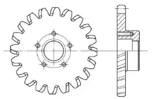
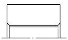
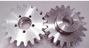
As shown in Figure 1, the helical gear to be processed has a 20° inclination and 20 teeth, and is made of LY12 material, as listed in Table 1. The challenge in this case is the lack of specialized equipment for processing gears on site of the competition. Each station is equipped with a four-axis processing center and is required to complete simulation and actual processing, as well as to produce a set of roller die mechanism combined with helical gear on site. The mechanism must work automatically when turned on and meet high gear matching requirements.
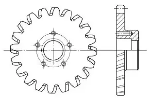
Figure 1 helical gear
| Tooth profile | Involve |
| Tooth inclination / (°) | 20/pair of teeth |
| Module | 4 |
| Number of teeth/piece | 20 |
| Graduation circle diameter/mm | 80 |
3. Method 1: general tool, stretch machining
CAXA Manufacturing Engineer software has a wide range of functions for four- and five-axis machining. To process the helical gear, the first step is to draw the gear geometry and then generate the tool path.
The following steps are involved in path generation:
- Select machining methods: “Machining → Five-Axis Machining → Five-Axis Limiting Surface Machining”, “Machining → Five-Axis Machining → Five-Axis Parallel Line” and “Machining → Path Editing → Five-Axis Trajectory for Four Axis.
- Define the roughing and finishing machining tools and choose the flat-bottom general cutter and the tapered spherical cutter to generate the roughing and finishing tool paths.
- Simulate the cut check, as shown in Figure 2.
a) Approximate machining path
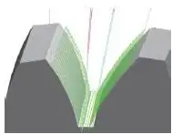
b) Finishing tool path
c) Simulate cutting effect
Fig. 2 Conventional helical gear machining tool path and cutting simulation
This process uses the five-axis tool path processing function, which is then transformed into a four-axis tool path to run on a more common four-axis machine tool. This process is used for one tooth and can be easily applied to other teeth by simply rotating the tool path. This method is highly adaptable, using conventional cutting tools to copy and cut along the curved surface, and can be applied to the processing of helical gears of other sizes.
However, this method has low processing efficiency and accuracy. The curved surface is produced through tool splitting, making it suitable for single-piece experimental processing or small-scale production. When batch processing, its weakness in terms of low efficiency and low accuracy becomes apparent. Therefore, it is imperative to find a more suitable processing method for batch processing of products.
4. Method 2: Customized cutting tools and profile processing
4.1 Tool customization
Using design software such as CAXA electronic drawing board, the relevant parameters of the helical gear can be entered into Table 1 to quickly obtain the tooth profile, and then the data can be extracted. Tooth profile CAD drawing data can be obtained based on the tooth profile and provided to the tool manufacturer to make customized gear knives.
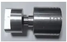
As shown in Fig. 3, the tool handle diameter is 12 mm, the length is 70 mm, and the cutting edge part is customized according to the tooth profile data. Although custom tools have a higher cost compared to general tools, they offer high processing efficiency, good quality, and overall benefits in batch processing.
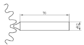
a pattern
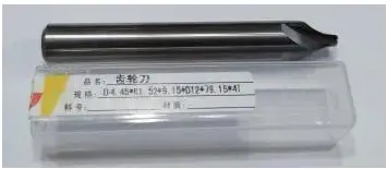
b) Physical object
Fig. 3 Custom Gear Cutter
4.2 Manufacturing of luminaires
Analysis of this part shows that it has a short clamping size, making alignment difficult and increasing processing time. Additionally, when machining the tooth profile, the tool and spindle are close to the four-axis chuck, increasing the risk of interference and making clamping and alignment challenging, making batch processing less convenient.
To improve processing efficiency, a customized fixture is required, as shown in Fig. 4. Fig. 4a is a movable part that fixes the gear blank through threads, ensuring that the clamping position is always fixed, reducing thus the tool adjustment time. Figure 4b shows the fixed part, which is fixed in the chuck. The actual accessory is shown in Fig.
a) Moving parts

b) Fixings
c) Physical object
Fig. 4 custom accessory
4.3 Machining graphic and tool path generation
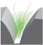
(1) To generate the tool path, draw a line with a slope of 20° between the bottom circle of the tooth and the helical gear. Then select “Machining → Four-Axis Machining → Four-Axis Cylindrical Curve Machining. Define tool and cutting parameters and generate the tool path. Other tool paths can be obtained through the path rotation matrix. The steps to generate the path are shown in Figure 5.
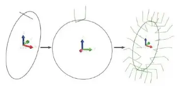
Fig. 5 Tool path generation
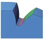
(2) To complete the machining process, generate the G code and check it using VERICUT. Select the tool path, generate G-code, and import it into VERICUT software to simulate the experimental cutting process (see Fig. 6a). After verification, import the code into the machine tool. The actual object obtained through cutting is shown in Fig.
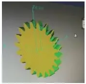
a) Simulated cut
b) Physical object
Fig. 6 Simulated cutting and machining
5. Conclusion
Typically, helical gears are machined on specialized milling machines and not as often on widely used CNC machining centers. This post explores the machining method of helical gears on a four-axis machining center and provides a preliminary exploration of the four-axis NC machining method for helical gears.
For single-piece or small-scale production, profile processing can be used. For batch processing, the use of custom tools is recommended. This method overcomes the limitation of processing helical gears on specialized equipment and can be applied to more widely used NC equipment currently available.