With the advancement of modern manufacturing technology, NC machining equipment and its supporting CAM system have become widely used and developed.
The core of controlling the machining operation of the equipment is the tool path (i.e., tool travel mode) generated by the CAM system.
This directly impacts the precision of the machined part, surface roughness, total machining time, machine tool life and, ultimately, production efficiency.
This post looks at the distinguishing features of the tool's power mode and some factors that influence its selection. It provides a reference basis for choosing the appropriate tool feeding mode based on a comparison of process methods and tool feeding modes in the milling process.

1. Tool feeding mode
Basic concept of tool feed mode
In NC machining, the term “tool path planning mode” refers to the way in which the tool path is planned during part cutting.
For processing the same part, various cutting methods can meet the size and precision requirements, but their processing efficiencies may be different.
Classification of tool feeding methods
Tool feeding methods can be categorized into four groups: unidirectional knife displacement, reciprocating knife displacement, ring cutting knife displacement and compound knife displacement. The last category, compound knife walking, is a mix of the first three methods.
These methods employ unidirectional or reciprocating tool displacement, which is known as line cutting tool displacement in terms of processing strategy.
Therefore, based on different machining strategies, tool feeding methods can be divided into line cutting, ring cutting and other specialized methods.
Line cutting and ring cutting are the most commonly used methods. In-line cutting processing allows maximum utilization of the machine tool's feed speed, leading to better cutting surface quality compared to ring cutting processing.
However, when processing complex planar cavities with multiple protrusions that form multiple internal contours, additional tool lifting actions may be required. This is necessary to avoid interference between the tool and the shoulder or to return the tool to the unprocessed area. The tool needs to be raised to a specific height on the machining plane, translated to the beginning of another tool path, and then continue the cutting process.
The tool path for linear cutting mainly consists of a series of straight lines parallel to a fixed direction, making its calculation simple. This method is ideal for simple cavity finishing or rough machining to remove excess material. An example of this is shown in Fig. 1 – alternative cutting rail.
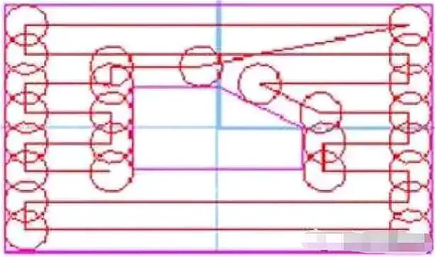
Fig. 1 Alternative cutting rail
In circular cutting, the tool moves along a path that has a similar boundary contour, consisting of a group of closed curves. This helps maintain consistent cutting conditions when machining parts.
However, the calculation for ring cutting is complex and time-consuming as it involves constructing the current ring diagram and continuously shifting it to calculate the next ring. Despite this, it is suitable for machining complex cavities and surfaces, as shown in Figure 2 – circular cutting rail.
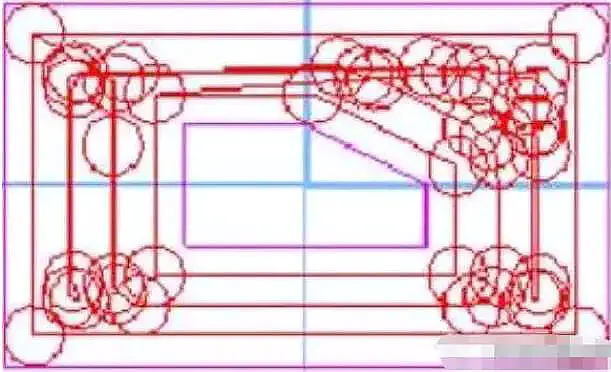
Fig. 2 Circular cutting rail
2. Factors affecting tool feeding mode
Shape and geometric elements of the piece itself
The geometry and shape of the part, including the machining area and the size and location of any islands, are inherent characteristics of the part that cannot be changed. These elements play a crucial role in determining how the tool is fed and are fundamental factors to consider.
Process route
The process route is the direct method to achieve the machining objective and serves as the main consideration for cutting mode selection.
Determines the sequence of processing areas, the combination and separation of islands and the division between roughing, semi-finishing and finishing machining.
There are many types of process routes that can achieve the desired result, and the choice of tool travel mode varies depending on the route chosen.
Part material
The material of the part is also a factor that influences the choice of tool displacement mode.
The workpiece material itself is the direct object of processing, but it does not directly affect the tool movement mode. However, it can impact the tool material selection, size and processing mode, which in turn can indirectly affect the tool travel mode.
The shape and size of the blank will determine the distribution of machining tolerances across different parts of the part. Furthermore, for parts with optional blanks, the use of different sizes and shapes of blanks can change the clamping mode and the distribution of machining areas, thus affecting the machining strategy and leading to different tool travel modes.
Method of fixing and clamping the workpiece
The clamping and clamping method of the workpiece can also indirectly affect the tool travel mode. This includes the creation of new “islands” due to the press plate, changes in tool travel mode caused by the impact of clamping forces on cutting parameters, and the influence of vibration on tool travel mode.
Selection of cutting tools
Tool selection includes factors such as tool material, shape, length and number of teeth.
These parameters influence the area and frequency of contact between the tool and the part, thus affecting the volume of material removed per unit of time and the machine load. Furthermore, wear resistance and tool life determine the period of time the tool can be used.
The size or diameter of the tool has a direct impact on the way the tool is fed. Choosing tools with different diameters will change the size of the residual area, change the machining path, and result in different tool travel methods.
Machining domain selection
In milling, when complex planar cavities have multiple protrusions that form multiple internal contours, additional tool lifting actions will frequently occur during linear cutting, and the machining path will become longer in circular cutting. These actions significantly reduce cutting efficiency.
To minimize the number of these occurrences, the cutting area is divided into several subareas based on machining needs. The tool lifting actions occur between these subareas. Subareas can be combined, divided or even ignored, depending on the tool movement mode. This helps to reduce the number of tool lifting actions and prevents the machining path from becoming too long.
Furthermore, by selecting the most appropriate tool travel mode for each subarea, machining efficiency can be improved.
3. Reasonable selection of tool feeding mode
Basic selection principle
Two factors must be taken into consideration when choosing the tool feeding mode: processing time and uniformity of machining tolerance.
In general, the circular cutting method is preferred for its uniform machining margin, which is determined by the shape of the part. On the other hand, the line cutting method results in non-uniform machining margin. To achieve uniformity in this case, the circular path of the cutting tool must be increased around the limit.
However, ignoring the uniformity requirement, the in-line cutting method has a relatively short tool path length. On the other hand, increasing the circular cutting tool path to solve the non-uniformity problem may result in longer total machining time, especially for long edges such as multi-island situations.
Although thread cutting is easier to calculate and requires less memory, it also involves more tool lifting. In contrast, circular cutting requires shifting the ring boundary several times and removing self-intersecting rings.
Selection according to shape features
The shape of the part determines the tool path in machining.
Based on the nature of the object being machined, the part can be broadly categorized into two types: flat cavities and free-form surfaces.
Flat cavities are typically machined using line cutting. This is because most parts of this type are created through cutting and milling processes, such as boxes, bases and other parts, which have large machining tolerances. Linear cutting allows maximum use of the machine tool's feed speed, resulting in greater machining efficiency. Furthermore, the surface quality produced through line cutting is better than that produced through ring cutting.
On the other hand, free-form surfaces are usually machined using ring cutting. This is because these surfaces are mostly cast or molded through regular processes, resulting in uneven residual distribution and high precision requirements. Furthermore, compared to line cutting, ring cutting provides better surface machining characteristics and can better approximate the actual shape of the surface.
Select according to machining strategy
The machining of parts is normally divided into three stages: rough machining, semi-finishing machining and finishing machining. This division is important to guarantee machining precision.
In traditional processing methods, the boundaries between each step are clear. However, in NC milling, these limits may be less defined due to the machine tool's ability to perform multiple functions. There may also be overlap between stages, such as fine machining performed during rough machining or rough machining traces remaining after rough machining.
Despite this, it is still necessary to divide the machining steps in NC machining to ensure quality. However, determining the machining content for each step may differ from traditional methods, as the objective is to reduce clamping time and simplify tool movement.
The main objective of rough machining is to maximize the material removal rate and prepare the geometric contour of the part for semi-finishing. Therefore, line cutting or compound methods are commonly used for layer cutting.
Semi-finishing aims to produce a flat contour and a uniform surface finish. Circular cutting methods are typically used for this phase.
The objective of finish machining is to produce a part that meets dimensional, shape accuracy, and surface quality requirements. Based on the geometric characteristics of the piece, line cutting is used for the interior and ring cutting for edges and joints.
Select according to programming strategy
The main considerations for determining the tool feed mode during programming are:
- Compliance with machining precision and surface roughness requirements of parts;
- Shorten the processing route to minimize tool travel idle time;
- Simple numerical calculation and reduction of the number of program segments to minimize programming effort.
For flat cavities, line cutting is used to divide the machining domain and minimize the number of tool lifts. On the other hand, free-form surfaces are approximated in the form of tangent rings.
The selection of the blank format also affects the choice of programming. By modifying the shape of the blank, the processing of shapes that are difficult to clamp can be transformed into in-line cutting cavity processing that is easier to clamp. Alternatively, freeform surface machining can be changed to linear cutting to remove larger gaps, thereby improving machining efficiency.