GUIDE
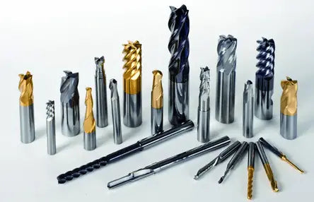
Milling tools are rotary tools with one or more cutting edges for machining. During operation, each cutting tooth removes a portion of the workpiece at intervals. The milling tool is mainly used for machining flat surfaces, stepped surfaces, grooves, formed surfaces and cutting workpieces.

And I believe that when selecting a milling tool, you need to pay attention to both the milling tool body and the tool holder:
- Whether the milling tools are used in a CNC machining center or a common milling machine.
- Milling material and hardness.
- Milling tool specifications such as: blade length, total length, blade diameter, shank diameter, etc.
When using CNC machining centers, it is recommended to use solid carbide tools. On the other hand, white steel can be used in common milling machines.
White steel milling tools have a softer composition compared to hard alloy tools. High-speed steel blades are economical and have good toughness, but their strength is not as high and they are more prone to wear and heat damage.
The high-speed steel milling tool has a thermal stability of about 600 degrees and a hardness of approximately 65HRC.
It is important to note that when milling hard materials with white steel, lack of coolant can easily lead to the blade burning, which contributes to its low thermal stability.
In contrast, carbide tools have high thermal stability and abrasion resistance, but have lower impact resistance and may break if dropped. Carbide is a material produced through powder metallurgy and has a hardness of around 90 HRA and thermal stability of 900-1000 degrees.
In conclusion, white steel milling tools are suitable for use with ordinary milling machines, while alloy milling tools are more suitable for CNC machining centers.
1. Selection of milling tool diameter
Milling tool diameter selection varies greatly based on the product and production batch size. The choice of cutter diameter depends mainly on the equipment specifications and the size of the part being processed.
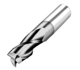
Simple milling tool
When selecting the diameter of a face milling tool, it is important to ensure that the power requirements of the tool are within the capabilities of the machine tool. The machine tool spindle diameter can also serve as a reference for this selection.
A general rule of thumb is to choose the face milling tool diameter as 1.5 times the spindle diameter (D = 1.5d).
In mass production, the tool diameter can also be selected based on 1.6 times the width of the material to be cut.
End mill
When choosing the diameter of an end mill, the main consideration should be the size of the part being processed and ensuring that the power requirements of the tool are within the capacity of the machine tool.
If the end mill has a small diameter, it is essential to consider whether the maximum rotational speed of the machine can reach the minimum cutting speed of the tool, which is 60 meters per minute.
Notch Cutter
The diameter and width of a slot milling tool should be selected based on the size of the workpiece to be processed, and make sure that the cutting power of the tool is within the power range of the machine tool.
2. Milling tool blade selection
(1). For fine milling, it is advisable to use a grinding insert. This type of insert has greater dimensional accuracy, leading to better positioning accuracy of the cutting edge, resulting in better machining precision and surface finish.
Furthermore, the trend in grinding and finish milling inserts is to grind the chip channel to form a cutting edge with a large positive rake angle, allowing the insert to cut at a low feed rate and depth of cut. Without sharp rake angles, carbide inserts can rub against the workpiece during low feed rates and depths of cut, leading to short tool life.
(two). In some machining situations, a pressed insert may be more appropriate and in others, a ground insert is required. For grinding operations, a pressed insert is recommended to reduce processing costs.
Although the dimensional accuracy and sharpness of a pressed insert are not as good as those of a ground insert, the edge strength of a pressed insert is better and can withstand impacts during rough machining and large cutting depths and feeds. Some pressed inserts also have chip channels on the rake face, which can decrease cutting forces and reduce friction with the workpiece and chips, thereby reducing energy requirements.
(3). However, the surface of a pressed insert is not as close as that of a ground insert, the dimensional accuracy is low, and the height of the tips on the milling tool body can vary greatly. Due to their low cost, pressed tablets are widely used in production.
(4). Sharp inserts with a large rake angle can be used to mill viscous materials such as stainless steel. The sharp edge reduces friction between the blade and the workpiece, allowing chips to move away from the front of the blade more quickly.
(5). Another option is to install a pressed insert into the blade seat of most milling tools and set up a grinding scraper insert. Using a scraping insert to remove rough machining marks can achieve better surface roughness than using just a pressed insert.
Additionally, using a scraper insert can reduce cycle time and cost. Scraping technology is an advanced technology that has been widely used in turning, grooving and drilling.
3. Milling tool body selection
Milling tools are relatively expensive, with a 100mm diameter face milling tool body costing more than US$600. It is important to choose carefully to meet specific processing needs.
(1). When selecting a milling tool, the number of teeth must be considered. For example, a 100mm diameter coarse tooth milling tool may only have 6 teeth, while a 100mm diameter dense tooth milling tool may have 8 teeth. The tooth pitch size affects the number of cutter teeth involved in cutting at the same time during milling, which in turn affects the smoothness of the cut and the requirements for the cutting rate of the machine tool. Each milling tool manufacturer has its own series of thick and dense tooth milling tools.
(two). Coarse tooth milling tools are mainly used for rough machining because they have a large chip channel. A small chip flute may cause difficulty in chip winding or increase friction between the chips, the cutter body and the workpiece. At the same feed rate, the cutting load per tooth of a coarse-tooth milling tool is greater than that of a dense-tooth milling tool.
(3). During fine milling, the cutting depth is typically shallow, 0.25 to 0.64 mm, and the cutting load per tooth is small (about 0.05 to 0.15 mm). The required power is not high, so a close-toothed milling tool can be chosen with a higher feed rate. Since metal removal is always limited in fine milling, a small chip channel in the dense tooth milling tool is not a problem.
(4). For spindles with larger tapered holes and better rigidity, rough milling can also be carried out with close-tooth milling tools. However, when using a large cutting depth (1.27 to 5 mm), it is important to consider the power and rigidity of the machine tool and the chip flute size of the milling tool. Chip removal must be checked by testing and adjustments made if necessary.
(5). During heavy rough milling, excessive cutting forces can cause chatter on less rigid machines, leading to chipping of carbide inserts and reduced tool life. Using coarse-toothed milling tools can reduce machine power requirements. Therefore, when the spindle hole size is small (such as R8, 30#, 40# tapered holes), a coarse tooth milling tool can be used effectively.