There are several accessories and devices necessary for the operation and safety of a boiler. Normally these devices are mounted on the boiler shell.
Boiler assembly functions:
These are the hardware that are mounted on the boiler for its proper functioning. They include water level indicator, pressure, pressure gauge, safety valve, etc. It may be noted that a boiler cannot operate safely without assembly.
According to the IBR below is the list of fixings that must be installed on boilers.
1. Water level indicators/water gauge
2. A pressure gauge
3. Safety valves
4. A steam shut-off valve or junction valve
5. A supply check valve
6. A blower dick
7. Fuse plug
8. A culvert, mud holes or view holes
9. Steam Scrubbers/Anti-Priming Tube
10. Air Blowers and Vacuum Breakers
11.Soot blowers
Main boiler supports and their functions:
Boiler Assemblies: Function 1) Feed check valveTo allow water flow into the boiler2) Water level indicatorTo check the water level in the boiler drum3) Purge cockTo draw water away from the boiler for maintenance purposes4) Pressure gaugeTo measure the pressure of steam generated in the boiler drum5) Steam stop valveTo control the flow of steam to the turbine6) Safety valveTo relieve excess steam from the boiler drum generated at high pressure7) Fuse plugTo extinguish fire in the furnace allowing spraying of water when melting the molten material
Water level indicators
Function
It is an important accessory, which indicates to the observer the water level inside the boiler. It is a safety device on which the correct functioning of the boiler depends. This accessory can be seen on the front of the boiler and is usually two in number.
Number and location: Two water level indicators/water gauges are normally installed in front of the boiler.
Construction of water level indicator:
It consists of three taps and a glass tube. Cock Stem 1 holds the glass tube in connection with the steam space. Water tap 2 connects the glass tube to the boiler water. Drain tap 3 is used at frequent intervals to check that the steam and water taps are clean.
Water level indicator diagram:
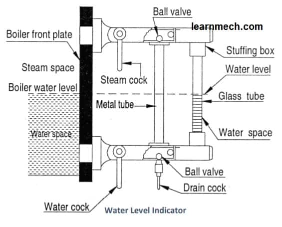 water level indicator diagram
How the water level indicator works:
When operating a steam boiler and for the water level indicator to function properly, the steam and water taps are opened and the drain tap is closed. In this case, the handles are placed in a vertical position. The rectangular passage at the ends of the glass tube contains two balls. If the glass tube breaks, the two spheres are transported along their passages to the ends of the glass tube. It is therefore obvious that water and steam will not escape. The glass tube can be easily replaced by closing the steam and water taps and opening the drain tap.
pressure gauge
Function
It is used to measure the steam pressure inside the steam boiler. The pressure gauges generally used are of the Bourdon tube type.
Number and Location: All boilers must be equipped with at least one pressure gauge and it is usually mounted on the top front of the boiler shell or drum so that the attendant can easily read the pressure reading.
There are two types of pressure gauges:
- Bourdon tube pressure gauge and
- Diaphragm type pressure gauge.
The common type of pressure gauge for steam boilers is the Borden pressure gauge, the construction and operation of which are described below:
Construction of the Borden manometer
It consists of an XYZ elliptical elastic tube bent into an arc of a circle, as shown in fig. This bent tube is called a Bourdon tube. One end of the meter is fixed and connected to the steam space of the boiler. The other end is fixed by links and pins to a toothed quadrant. This quadrant engages with a small pinion on the central spindle.
Borden pressure gauge diagram:
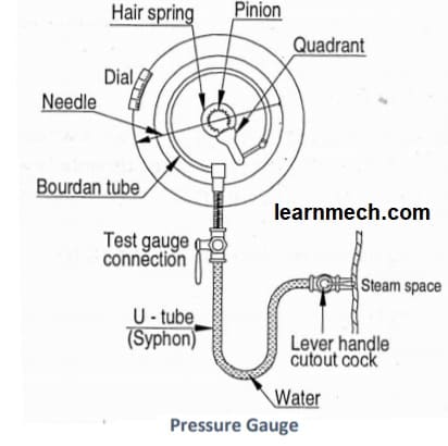 Bourdon pressure gauge diagram
How the Borden manometer works
Steam under pressure flows into the tube. As a result of this increased pressure, the tube tends to straighten. Because the tube is wrapped in a circular bend, it tends to become circular rather than straight. With the help of a simple pinion and sector arrangement, the elastic deformation of the Bourdon tube rotates the pointer. This pointer moves over a calibrated scale, which directly provides the gauge pressure.
Safety valves
Function: The function of a safety valve is to prevent the build-up of excessive pressure in a steam boiler. If the steam pressure in the boiler drum exceeds the working pressure, it allows boiler steam to escape to the atmosphere until the safe working pressure in the boiler is again reached. The safety valve also warns the boiler attendant when steam escapes through the safety valve.
Principle: The working principle of a safety valve depends on the valve being pressed against a seat by some external force. When the steam force corresponding to the boiler pressure acting under the valve exceeds the external force, the valve is lifted from its seat allowing part of the steam to escape until the working pressure is restored again.
Number and location: According to boiler regulations, each boiler must be equipped with at least two safety valves. Safety valves are located above the boiler steam space.
Types: There are four types of commonly used safety valves as given below:
(i) Dead weight safety valve,
(ii) Spring-loaded safety valve,
(iii) Safety valve lever and
(iv) High steam and low water level safety valve.
The choice of a safety valve for a particular boiler depends on the type of boiler and its safe working pressure.
Lever safety valve
A lever safety valve used in steam boilers is shown in fig. A lever safety valve consists of a valve body with a flange attached to the steam boiler. The bronze valve seat is bolted to the body and the valve is also made of bronze. The impulse on the valve is transmitted by the support. The guide keeps the lever in a vertical plane.
When the steam pressure exceeds the safe limit, the upward thrust of the steam lifts the valve from its seat. This allows the steam to escape until the pressure returns to normal. The valve then returns to its original position.
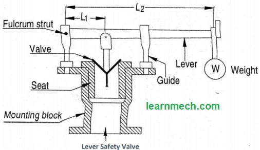 Lever safety valve diagram
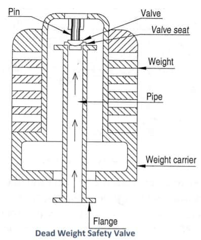
Dead weight safety valve
When the steam pressure exceeds normal limits, this high-pressure steam creates an upward force on the valve, causing the V-valve to lift under its weight and excess steam to escape through the tube to the outside.
 Deadweight Safety Valve Diagram
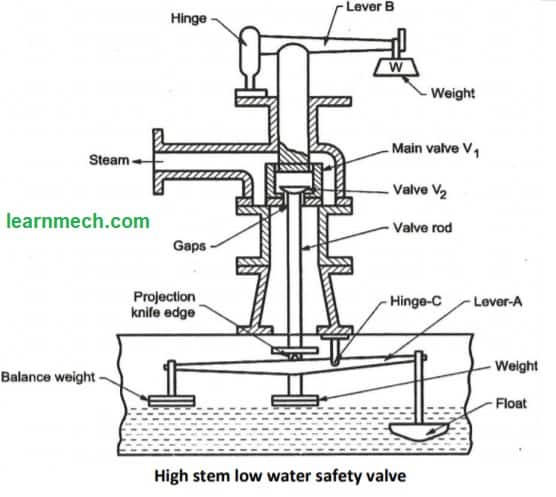
High Steam Low Water Safety Valve
This valve has a combined safety device against
a) high steam pressure in the boiler and
b) low water level in the boiler.
It allows steam to escape from the boiler when the steam pressure exceeds the normal value or the water lever in the boiler drops below the normal level. It consists of lever A which is hung inside the boiler shell and is hinged at point C. One end of the lever carries a balancing weight and the other end carries an earth float immersed in water. The balance weights are held in such a way that the tip of the lever just touches the projection when the float just dips into the water. It also consists of two valves. One is the V1 main valve that rests on its seat. The edge of the central opening in valve V1 forms the seat for the hemispherical valve V2 and the end of the valve stem carries a weight.
 High and low resistance stem safety valve diagram
When the water level drops and the floats are sufficiently uncovered from the water, the weight of the float increases and no more. It is balanced by the balance weights. Consequently, the floating end of the lever will move down and cause lever A to oscillate. When the lever oscillates, the valve stem will be pushed upward. It also pushes the hemispherical valve V2 upwards and the steam leaks through the gaps with a loud noise. This acts as a warning to the boiler attendant. When the hemispherical valve is closed, the main valve V1 acts as an ordinary lever safety valve and protects against high pressure in the boiler. Valve V1 is held in position partly by the weight on the valve stem V2 and partly by the lever carried above the valve body.
When the steam pressure exceeds the working limit pressure, the main valve V1 together with valve V2 rises and steam leaks through the discharge duct.
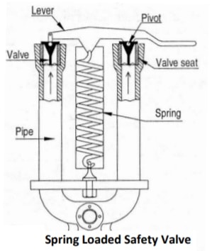
Spring safety valve
A Ramsbottom spring-loaded safety valve is shown in Fig. It is usually installed on locomotives. This valve consists of a cast iron body with two branches. Two valves sit in corresponding valve seats at the ends of the tubes. The lever is placed over the valves using two pivots. The lever is held firmly in position using a compression spring. One end of this spring is connected to the lever while the other end to the valve body.
Under normal conditions, the spring pulls the lever down. This applies a downward force to the valves that is greater than the upward force applied by the steam. When the steam pressure exceeds the normal value, the upward force becomes greater than the downward force on the valve due to the spring. Thus, the valves are lifted from their seats, opening the passage for the steam to escape. The valve closes due to spring force when the pressure in the boiler returns to normal.
 spring safety valve diagram
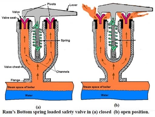
Operation:
When the steam pressure in the boiler is equal to the working pressure:
The upward force exerted by the boiler steam on the valve is balanced by the downward force of the spring. In this condition, the valve is well supported on its seat and the steam will not escape from the boiler as shown in Fig.
When the steam pressure in the boiler is higher than the working pressure:
The upward force exerted by the boiler steam on the valve is dominated by the downward force of the spring. In this condition, the valve opens automatically and the vapor escapes into the atmosphere (Fig. (b)) until the pressure returns to the working pressure.
 spring-loaded safety valve operation
Uses:
These valves are suitable for low and high pressure boilers, stationary and non-stationary boilers
Advantage:
- Heavy weight elimination.
- Easy maintenance and examination.
- It is not affected by bumps and vibrations.
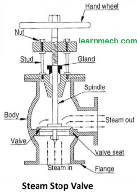
Steam stop valve or junction valve
Function
- To control the flow of steam from the boiler to the main steam pipe.
- To completely turn off the steam when necessary.
Location: This valve is usually mounted on the boiler drum, on the steam pipe leading to the steam turbine/engine, and between the steam pipes to stop or regulate the flow of steam.
Steam Shutoff Valve Construction:
The shut-off valve body is made of cast iron or cast steel. The valve, valve seat and nut through which the valve spindle operates are made of brass or metal. The spindle passes through a gland and a stuffing box. The spindle is rotated using a handwheel. Spindle rotation causes the valve to move up and down.
Steam Stop Valve Diagram
 Steam Shutoff Valve Diagram
Steam stop valve operation:
When the valve rests on the valve seat, the steam passage is completely closed. The passage can be partially or fully opened to the steam flow by moving the valve upwards by turning the handwheel.
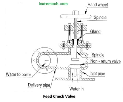
Feed Check Valve
Function: The function of the supply valve is
- To control the supply of feed water to the boiler from the feed pump and
- To prevent water from escaping from the boiler in case of supply pump failure or pump pressure lower than that on the boiler side.
Location: It is mounted on the boiler body, slightly below the normal boiler water level.
Feed Check Valve Construction:
It is a non-return valve, mounted on a screwed spindle to regulate the elevation. This valve must have its spindle lifted before starting the pump. Pump pressure acts below the check valve and boiler pressure acts above it. Under normal working conditions, the pump delivery pressure is higher than the boiler pressure. Thus, the valve is lifted from the seat and allows water to flow into the boiler. Valve lift is controlled by moving the spindle up and down with the help of the handwheel. Thus, the water flow can be controlled.
Supply Check Valve Diagram:
 Feed Check Valve Diagram
Feed check valve operation:
If the boiler pressure is higher than the pump pressure or if the pump is stopped, the upward force on the check valve is greater. Then he sits down on the seat and closes the passage. Therefore, the boiler water cannot flow backwards.
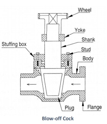
Blow a dick
Function:
The purge tap has three purposes: –
(i) To blow out sediment, precipitated sludge, loose scale or other impurities periodically when the boiler is in operation.
(ii) Empty the boiler when necessary for cleaning, repair and inspection.
(iii) Allow a rapid lowering of the water level in the boiler if it accidentally becomes too high.
Location: The purge tap is installed in the lowest water space of the boiler shell.
Purge valve construction:
A common type of purge cock is shown in fig. A conical plug is precisely fitted into a similar housing. The plug has a rectangular opening. The plug groove is perpendicular to the flow passage.
Purge valve diagram:
 Dick blowing diagram
Purge valve operation:
When the plug groove is aligned with the flow passage of the body by rotating the plug, the boiler water comes out with great force. If it is necessary to remove sediment, the purge tap is activated when the boiler is on. This forces the sediments to exit the caldera quickly.
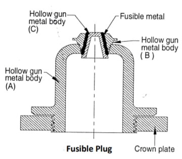
Fuse Plug
Function
The main function of the fuse plug is to extinguish a fire when the water level in the boiler drops below an unsafe level.
Location: The fusible plug is usually inserted into the furnace crown or combustion chamber at the lowest allowable water level.
Fuse plug construction:
The construction of the fusible plug is shown in fig. which consists of three plugs. The hollow plug A with hexagonal flanges is screwed to the furnace crown plate. Metal plug B is screwed into body A. The third plug C is made of copper and locked with metal such as tin or lead, which has a low melting point.
Fuse plug diagram
 Fuse plug diagram
Function of the fuse plug:
Under normal working conditions, water covers the fusible plug and remains cold. If the water level drops below danger levels, the fusible plug is exposed to steam. This overheats the plug and the low melting point fusible metal melts quickly. Due to this S plug falls out. The opening thus made allows steam to rush into the furnaces and put out the fire or warn the boiler attendant that the furnace crown is in danger of overheating.
Manhole and hand hole
Function: Manholes and hand holes are necessary for boiler cleaning, inspection and repair. The hatch is provided for the entry of a man into the boiler hull, while the hatch is for the hand.
Location: The manhole is placed in the boiler shell in a convenient location.
Construction: They are generally elliptical in shape and a cover is provided. The size of the culvert is generally 400mm x 300mm.
Read more about boiler:
- Types of boilers How are boilers classified?
- Introduction to Boilers Classification of boilers