Introduction to Fluid Coupling:
It is a device for transmitting rotation between axles through the acceleration and deceleration of a hydraulic fluid (such as oil). Also known as hydraulic coupling. Structurally, a hydraulic coupling consists of an impeller on the input or driving shaft and a rotor on the output or driven shaft. Both contain the fluid. The impeller and rotor are bladed rotors, the impeller acting as a pump and the rotor reacting as a turbine. Basically, the impeller accelerates the fluid from close to its axis, where the tangential component of absolute velocity is low, to close to its periphery, where the tangential component of absolute velocity is high. This increase in speed represents an increase in kinetic energy. The fluid mass emerges at high speed from the impeller, collides with the rotor blades, releases its energy and leaves the rotor at low speed.
Fluid Coupling Diagram:
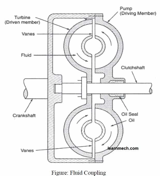 fluid coupling parts diagram
Fluid Coupling Parts:
Fluid or hydraulic coupling is used as clutches in cars that use automatic transmissions. It consists of two members, the actuator and the driven one as shown in fig. The driving member is attached to the engine flywheel and the driven member to the transmission shaft. The two members do not have direct contact with each other. The driven member can slide freely on the splines of the drive shaft. The two rotors are always filled with oil.
A hydraulic coupling consists of three components in addition to hydraulic fluid:
- The casing, also known as the shell (which must have an airtight seal around the drive shafts), contains the fluid and turbines.
Two turbines (fan-like components):
- One connected to the input shaft; known as pump or impeller, primary wheel input turbine
- The other connected to the output shaft, known as the turbine, output turbine, secondary wheel or rotor
Fluid coupling work:
When the crankshaft rotates, the driving member or impeller also rotates. The driving member is filled with oil and centrifugal force causes the oil to be forced outward radially. As a result of this, the driven member or turbine is forced to rotate. Thus, engine power is transmitted from the crankshaft to the drive shaft.
As the engine speed increases, the oil expelled from the driving member hits the driven member with greater force and tends the driven member to rotate at the same speed, becoming a unit through an oil film that combines both members . As the engine speed decreases, the oil film between the driving and driven members is broken and the members are disengaged.
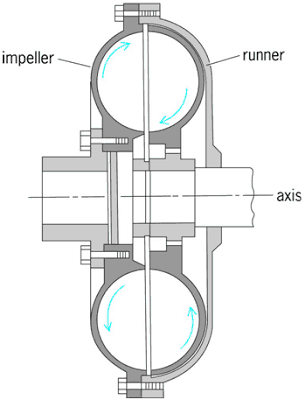 Fluid Coupling Construction and Work
- The driving turbine, known as the 'pump , is turned by the main engine, which is typically an internal combustion engine or electric motor. The movement of the impeller imparts outward linear and rotational motion to the fluid.
- The hydraulic fluid is directed by the 'pump' whose shape forces the flow towards the 'output turbine'.
- Here, any difference in the angular velocities of the 'input stage' and the 'output stage' results in a net force on the 'output turbine' causing a torque; causing it to rotate in the same direction as the bomb.
The fluid motion is effectively toroidal – traveling in one direction in paths that can be visualized as being on the surface of a torus:
Difference Between Torque Converter and Fluid Coupling
Mr. no. Torque Converter Fluid Coupling 1. The main components are pump, stator and turbine. The main components are the impeller and runner. have step. The blades are just fins. 4. It acts as an automatic clutch and serves the purpose of an automatic gearbox to increase torque. It accelerates, but is a little more efficient under load. It's efficient at highway speeds. 6. It is generally used in conjunction with automatic clutch (mainly flywheel fluid) to eliminate the slight loss of efficiency at highway speeds. clutch.7.It never locks and the oil flow never stops but continues. The impeller and runner are locked and oil movement stops during engagement when the centrifugal force is approximately the same in both members.
Advantages of fluid coupling:
The following are the advantages of fluid coupling
- Controlled starting speed without shock load of power transmission system
- There is no mechanical contact between the driving shaft and the driven shaft (or between the pump wheel and the turbine wheel). Therefore, there is no frictional wear on them.
- Power transmission is smooth. The motor or motor starts without load.
- Fluid coupling can dampen shock loads. Fluid coupling can work smoothly even in extreme conditions.
- Power transmission is vibration-free. There is no chance of vibration noises when power is transmitted from the vibrating motor to the driven shaft using a hydraulic coupling.
- Fluid coupling can be used in vertical and horizontal applications.
Disadvantages of Fluid Coupling:
- There is always a slippage. There is always a slight difference in the speed of the pump wheel and the turbine wheel
- The fluid-filled housing must be compatible with the coupling component, as it directly affects the transmission behavior of the hydraulic coupling.
- The fluid coupling cannot develop torque when the drive shaft and driven shaft are rotating at the same angular speed.
- Under locked conditions, the coupling dissipates energy in the form of heat, which can cause damage.
Application of fluid coupling:
Read too:
- What is flywheel fluid Diagram, Advantages and Disadvantages
- Torque Converter – Operation, Parts, Diagram, Advantages, Application