This article examines the welding defect that easily creates pores when welding copper-nickel alloys. small diameter pipe and analyzes them point by point from the perspectives of automation equipment, welding wire diameter, welding shielding gas, welding environment, welding process parameters, welder operator skills, etc., judges the main reasons that affect its qualification rate and formulate targeted countermeasures to improve the qualification rate of thin-walled copper-nickel pipelines improves.
0. Introduction
In the natural gas compressor sled of the offshore production platform, the seawater cooling system inside the sled uses a large number of thin-walled copper-nickel pipelines with thicknesses of 19.05 mm, 12.7 mm and 2 .5mm and small diameter. Copper-nickel alloys have unique physical properties and present technical difficulties in welding, such as: B. Difficulty in fusion, deformation due to high welding stresses and easy occurrence of defects such as hot cracks and pores. In the actual production project, through the study and statistics of first welding pass rate data and RT plates, it was found that pores are the main welding defect in small diameter thin-walled pipelines. According to the standard, it needs to be repaired when the pore diameter exceeds 1/3 of the thickness of the base material. Therefore, for pipes with a wall thickness of 2.5 mm, the standard is exceeded when the pore diameter reaches 0.75 mm. When welding this small diameter tube, the inclination angle of the welding gun changes greatly, making it difficult to control the process, which can easily cause poor gas shielding in the weld pool and the formation of pores. In order to solve the technical problem of welding small-diameter thin-walled copper-nickel alloys, the author has continuously innovated and accumulated practical design experience in welding environment, pre-welding assembly, welding process, deformation control, etc., and summarized a complete set of guarantee measures. Technological innovations have been carried out, especially in the areas of gas shielding and pre-welding preheating, to effectively guarantee the first pass rate of welding.
1. Storage of copper-nickel alloy materials (tube fittings, pipelines) and welding materials
metal materials should be placed in designated areas away from the polishing area to avoid contamination and stored on rubber or skids as shown in Figure 1. Welders should use welding materials properly in accordance with the requirements of welding process regulations, and the welding materials must be obtained from the warehouse. It is strictly prohibited to store welding materials without authorization.

Figure 1 Insulation and placement of copper-nickel alloy materials
According to the welding characteristics of copper-nickel alloy materials, the welding method should be argon arc welding, with concentrated arc heat and high welding quality. Table 1 shows the recommended welding process parameters (for each layer of welding material, 2.0mm LNTCuNi30 welding wire is used and the power polarity is DCSP).
Table 1 Welding process parameters
| Welding process | Current/A | arc voltage/ v | Gas flow/(L . Minimum -1 ) | Welding speed/(mm.min -1 ) | Heat input/(kJ.min -1 ) |
| TIG | 70 – 90 | 11 – 13 | 12 – 20 | 20 – 35 | 2.3 |
| TIG | 80 – 110 | 12 – 14 | 12 – 20 | 30 – 50 | 2.6 |
| TIG | 80 – 110 | 12 – 14 | 12 – 20 | 30 – 50 | 2.6 |
3. Welding environmental requirements
- (1) Control wind speed below 2 m/s and take wind protection measures.
- (2) Control relative humidity below 85%.
- (3) The welding area is dust-free and clean, and the welding personnel are equipped with shoe covers.
- (4) The construction site area must be well ventilated due to the release of argon gas during welding.
4. Preparation before welding
4.1 Groove and assembly
- (1) The shape of the groove must meet the requirements of the design drawing or regulation, and the processing of the groove must be done mechanically or with a stainless steel grinding machine.
- (2) Before welding, the internal and external surfaces must be cleaned manually or mechanically. Slag, oxide scale, oil stains or other contaminants must be carefully removed from both sides of the groove. Use a stainless steel grinding wheel to polish the groove and a stainless steel mushroom head to polish the inside. Before welding, clean the welding point groove with a stainless steel brush and then with acetone.
- (3) The mounting clearance should be controlled above 3mm and the misalignment should be less than 1mm. If the local gap of the joint is too large, efforts should be made to shorten it to the specified size, and the addition of fillers within the gap is strictly prohibited.
- (4) Group correspondence is carried out on a form suitable for this purpose, protected with rubber or similar materials.
- (5) The misalignment of the inner wall of the pipeline must be ≤ 0.5 mm and the misalignment of the outer wall must be ≤ 1 mm.
4.2 Preheating
- (1) An electric heater must be used as shown in Figure 2. Flame heating is not allowed to avoid weld contamination caused by flame heating, and the preheating temperature must be above 20°C.

Figure 2 Preheating with Electric Heating Tape
- (2) The preheating area is at least 75 mm around the groove. After preheating, measure the temperature with a thermometer. Welding can only be carried out after reaching the required preheating temperature or higher.
- (3) When repairing, the preheating temperature should be 50°C higher than the preheating temperature when welding the original weld.
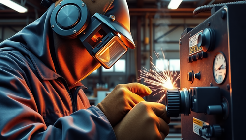
5. Welding
5.1 Spot welding
- (1) Weld seams in positional welding must be made by qualified welders.
- (2) The same welding materials and process parameters apply to positional welding and formal welding requirements.
- (3) 20mm for positioning welding × 10mm copper-nickel alloy plate; When spot welding and removing spot welding seams, the base material must not be damaged.
- (4) To reduce the storage time after assembly, welding should be carried out within 4 hours to avoid oxidation pollution on the surface of the base material.
5.2 Argon landfill
- (1) Use water-soluble paper or sponge on each edge close to the weld, keeping a minimum distance of 150 mm from the edge of the weld.
- (2) Sufficient gas pressure must be maintained within the tube to allow oxygen to be released from the outside. The pressure inside the tube must be maintained above the external atmospheric pressure.
- (3) The shielding gas supply can only be stopped after welding the second layer, and the thickness of the welding layer is 1/4 of the pipe wall thickness.
- (4) During the welding process, the oxygen content in the line must be checked using an oxygen measuring device. The oxygen level must be below 70 × 10-6.
- (5) The shielding gas flow should be gradually increased from 35% to 70% of the chamber volume within 5 minutes to prevent the formation of an air chamber.
- (6) Test argon purity to ensure 99.99% purity.
5.3 Control of the welding process
- (1) During the welding process, the end of the welding wire must not leave the argon protection zone. The angle between the welding wire and the welding surface should be about 15° when inserted, and the angle between the welding gun and the welding surface should be maintained between 80° and 90°.
- (2) The arc must be ignited and extinguished within the groove. During arc extinguishing, argon gas must be supplied to the extinguishing point for another 10 seconds. The length of the tungsten electrode should be limited to less than 5 mm to avoid poor gas shielding effect.
- (3) After sealing the root weld, check whether the root weld is oxidized. If it's light brown, it qualifies; If the surface of the root weld is oxidized, it is considered unqualified. If it is blue-gray, it must be reassembled for welding.
- (4) To ensure good weld penetration or fusion, low current, short arc, high speed welding and multi-pass welding methods should be used. The interlayer temperature must be kept as low as possible, below 100 °C. Oxide layers, solder joints and other welding defects between layers must be thoroughly cleaned mechanically or with a stainless steel brush.
- (5) When copper-nickel alloy welding wire is used for welding, the welding wire is easy to oxidize after heating. Before welding again, the oxidized part of the welding wire must be cut off before continuing welding.
- (6) If tungsten contact occurs during tungsten arc welding, welding must be stopped and the tungsten electrode, welding wire and arc crater must be cleaned before continuing welding. As the arc extinguishes, the welding gun is gradually lifted off the workpiece and continues to feed wire to fill the arc well. Then the molten pool is formed into a tail shape and the welding gun operation switch is turned off. However, the welding gun cannot be evacuated immediately, but must wait for the welding arc extinguishing area to cool down before evacuating, so that this area continues to be protected by argon gas.
- (7) After welding, carefully clean the welding surface with a stainless steel brush. If there are defects such as lack of fusion or porosity, weld again.
- (8) The surface of the weld seam should not be deeper than the surface of the pipeline.
5.4 Deformation control
- (1) Make sure that the gap, blunt edge and groove angle of the entire weld groove are almost the same. To a certain extent, ensure that different positions have the same amount of metal filler, which reduces the deformation caused by different amounts of shrinkage.
- (2) When welding pipelines or pipe fittings To ensure good fixation, consider using structural scaffolding such as wooden blocks.
- (3) For pipelines with large mass and long length, at least three layers or 6 mm of metal filler must be applied before moving to avoid bending deformations caused by the gravity of the pipeline itself.
- (4) When welding the root weld, the weld is divided into four parts, starting from 6-9 o'clock, 3-0 o'clock, 6-3 o'clock and 9-12 o'clock. The author welds sequentially to control the welding deformation caused by the shrinkage stress of the root weld.
- (5) If the circularity deviation of deformed pipelines or pipe fittings exceeds 8% of the outer diameter, mechanical adjustment methods must be used. The weld must be removed and reassembled for welding if it cannot be restored. Before cutting the weld, permission must be obtained from the owner and the procedure for repairing the weld must be followed.
5.5 Welding repair
- (1) Excessive defects in the welded joint can be repaired by repair, but the number of repairs in the same location should not exceed two.
- (2) Certified and qualified welders must perform welding repairs for the corresponding qualified projects.
- (3) Before repairs, the type, length and width of defects must be analyzed and the location of the defect must be confirmed.
- (4) When repairing, defects must be completely removed, and the shape of the groove must be as regular as possible to avoid sharp corners, sudden contour changes and burrs at the bottom of the groove.
- (5) The welding process used for repair must be in accordance with the formal welding process. The preheating temperature during repair should be set to the upper limit of the preheating temperature, and the heating range should also be expanded accordingly.
- (6) The surface of the repair weld must be repaired and polished to ensure that its appearance is consistent with the original weld.
- (7) Upon completion of the repair, the repaired weld area shall be inspected to a quality standard no lower than that of the original weld. If unacceptable defects are found, they must be repaired again.
- (8) For defects that cannot be repaired by spot repair welding, the weld joint can be cut and the groove reworked before welding.