In metal cutting operations, some chips form spirals, automatically breaking at a certain length; others fold into C- or S-shaped fragments.
Some take the form of spring-like spirals, while others fragment into small or needle-shaped pieces, spreading far and wide, compromising safety.
Ribbon-like shavings can wrap around tools and workpieces, posing a risk of accidents. Poor chip control can impede normal production.
Factors influencing chip formation
1. Workpiece material
The alloying elements, hardness and heat treatment status of the workpiece material affect the thickness and curvature of the chips. Mild steel forms thicker chips than hard steel, and hard steel is less prone to curling.
Chips that do not curl easily are thin, but mild steel also resists curling when the chip thickness is too large. The external shape of the part is another significant factor.
2. Geometric Parameters of the Tool Cutting Zone
Appropriate geometric parameters of the tool cutting zone are the most common method for improving chip formation control and chip breaking reliability.
The rake angle is inversely proportional to the chip thickness and has an ideal value for different materials being machined; The main rake angle directly influences chip thickness and width, with a large angle making chip breaking easier.
The arc radius of the tool tip is related to the chip thickness and width and the chip flow direction.
Fine machining is suitable for smaller radii, while rough machining is more suitable for larger radii.
The width of the chip breaking groove is selected proportionally according to the feed rate – a narrow one for a small feed rate and a wider one for a large feed rate.
The depth of the chip breaking groove is selected inversely according to the feed rate – a deep one for a small feed rate and a shallow one for a large feed rate.
3. Cutting parameters
The three elements of the cutting parameters define the chip removal range.
Feed rate and further depth of cut have the most significant impact on chip removal, while cutting speed within the standard range has the least effect.
The feed rate is directly proportional to the chip thickness; the subsequent cutting depth is directly proportional to the chip width; chip speed is inversely proportional to chip thickness. Increasing the cutting speed reduces the effective chip removal range.
4. Machine tools
Modern CNC machine tools employ NC editing functions to periodically adjust the feed rate, achieving what is typically called “program-controlled chip removal.”
This method is highly reliable for chip removal, but is less economical in terms of cutting. It is commonly used in operations where chip removal is challenging, such as end face turning and deep grooving.
5. Cooling and lubrication conditions
The addition of cutting fluid extends the effective chip removal range, particularly noticeable when small feed rates easily cause chip curl.
Using high-pressure cutting fluids for chip breaking and removal is an effective method in certain machining processes, such as deep drilling, where high-pressure cutting fluids can expel chips from the cutting area.
The process of forming the chip shape
The strip-shaped chip formation process can be divided into three steps:
1. Basic Deformation Stage:
This is the phase where the metal layer to be cut begins to interact with the cutting edge of the tool, leading to the detachment of the chip from the part material.
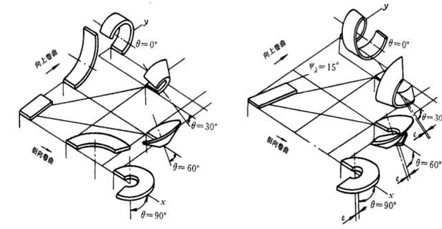
2. Ripple deformation stage:
These include upward curl, sideways curl, and tapered curl that involves the A and B directions.
3. Additional Stage of Deformation and Fracturing.
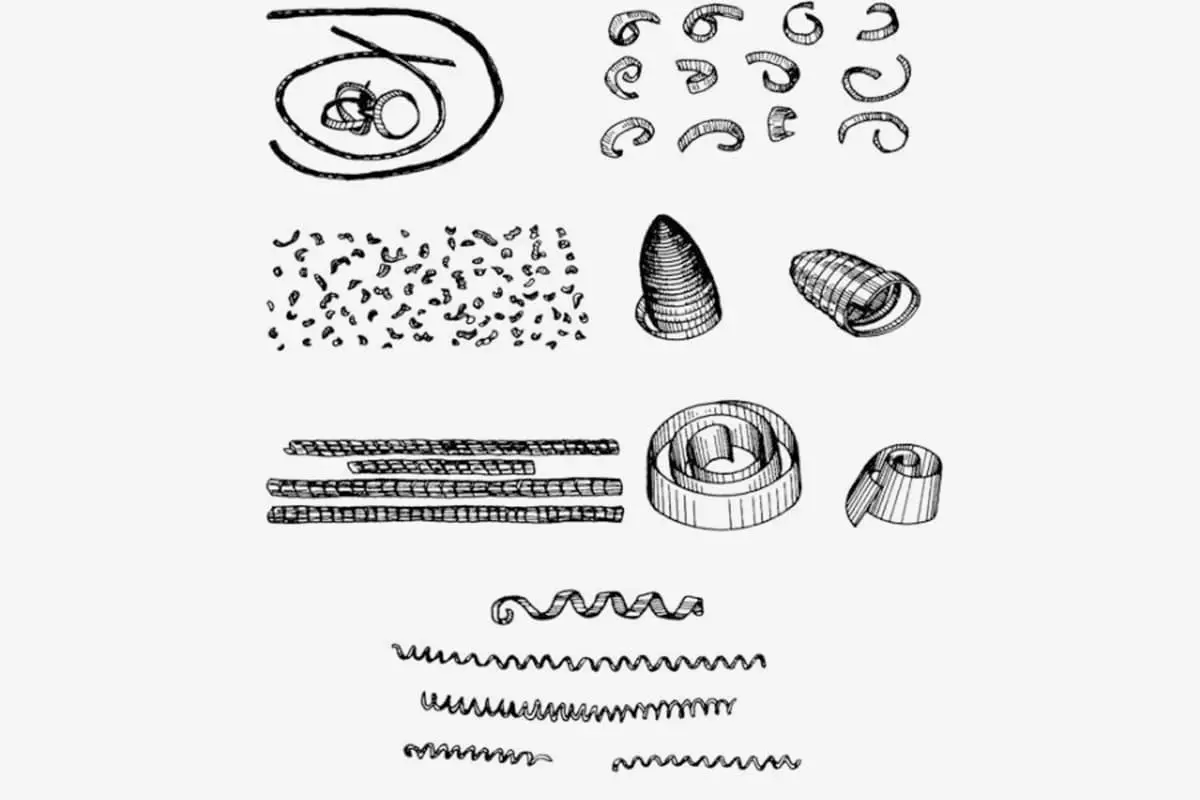
Chip classification
Given variations in workpiece materials and cutting conditions, a wide variety of chip shapes are produced during the cutting process.
The main chip formats can be categorized into ribbon, segmented, granular and fragmented, as shown in the figure.
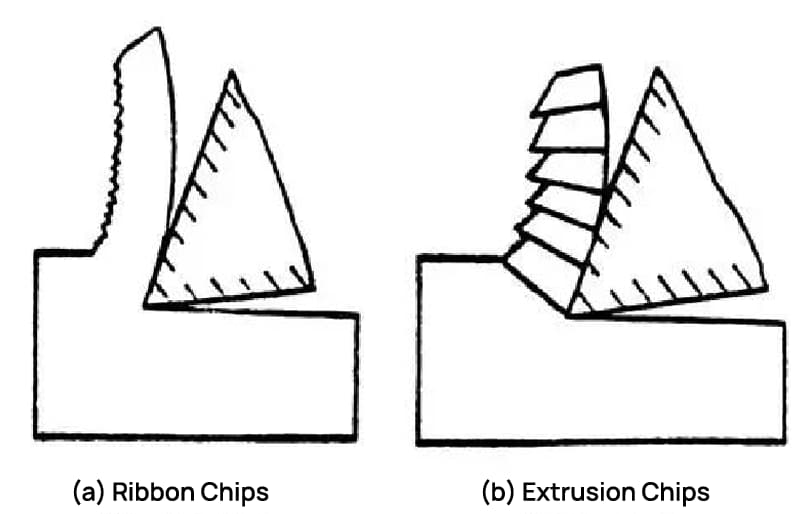
1. Ribbon-shaped chips
This is the most common type of chip. The inner surface is smooth and the outer surface is fluffy.
When machining ductile metals, under conditions of small cutting thickness, high cutting speed and larger tool rake angle, this type of chip often forms. The cutting process is balanced, with less fluctuation in cutting force, and the machined surface has lower roughness.
2. Segmented chips
Also known as crushed chips. The outer surface is serrated and the inner surface sometimes has cracks. This type of chip generally forms when the cutting speed is lower, the cutting thickness is higher and the tool inclination angle is lower.
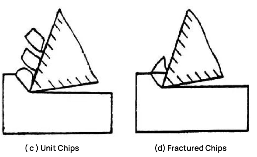
3. Granular chips
Also known as unitary chips. In the chip formation process, if the shear stress in the shear plane exceeds the fracture strength of the material, the crack extends across the entire surface and the chip unit falls out of the cut material, forming granular chips, as shown in the figure W.
The above three types of chips can only be obtained when processing ductile materials. Among them, the ribbon-shaped chip cutting process is the most stable, and the fluctuation of the cutting force of unit chips is the largest.
In production, ribbon-shaped chips are the most common, crushed chips are sometimes obtained, and unitary chips are rarely seen.
If the conditions for crushed chips are changed, such as further reducing the tool rake angle, reducing the cutting speed, or increasing the cutting thickness, unit chips can be obtained. On the other hand, ribbon-shaped chips can be obtained.
This indicates that the chip shape can be transformed with the cutting conditions. Once the change rule is mastered, the chip deformation, shape and size can be controlled to achieve the objective of chip curling and breaking.
4. Formation of brittle chips
This type of chip formation occurs in brittle materials. The chips are irregular in shape, resulting in a rough and uneven machined surface.
In the cutting process, these chips undergo minimal deformation before fracturing, which differentiates them from chips formed by ductile materials.
The brittleness is mainly due to the applied stress that exceeds the tensile limit of the material. Hard, brittle materials such as high-silicon cast iron and white cast iron often produce these chips, especially when the cutting thickness is substantial.
The cutting process is unstable, can damage the tool, damage the machine tool and roughen the already machined surface.
Therefore, it should be avoided in production. Methods to avoid this include reducing the cutting thickness, causing the chips to form into a needle or sheet shape, and appropriately increasing the cutting speed to increase the ductility of the workpiece material.
The above are four typical types of chips, but chips obtained from the processing site come in various forms.
In modern cutting operations, cutting speed and metal removal rate have reached high levels, creating severe cutting conditions that often produce a substantial amount of “unacceptable” chips.
Appropriate measures must be taken in cutting processes to control chip curl, flow and breakage, resulting in the formation of “acceptable” and well-shaped chips.
The most widely used chip control method in actual processing includes grinding a chip breaking groove on the front face of the tool or using a clamp-type chip breaker.