In essence, positioning and fixing have only one purpose: to prevent deformation.
When machining parts, the question arises: should fixing or positioning come first?
This is a summary that industry professionals have extracted from equipment design, but the reality is far from simple. We have found that preliminary designs are often insufficient in managing positioning and securing.
As a result, even the most innovative solutions lose their practical value. Understanding the basics of positioning and fixture can fundamentally ensure the integrity of fixture design and machining plans.
Knowledge of locators
1. Basic principles for lateral positioning of a workpiece
When positioning a workpiece laterally, as with supports, the three-point principle is basic.
This principle, known as the three-point principle, is derived from the concept that “three non-collinear points determine a plane”. In a set of four points, three points can determine a plane, thus potentially defining four planes in total.
However, no matter how the positioning is done, aligning the fourth point on the same plane is a significant challenge.
For example, when using four fixed-height locators, it is highly likely that only three points will contact the workpiece, leaving the fourth point without touching the workpiece.
Therefore, when setting up locators, it is common to use three points as a base and maximize the distance between these three points as much as possible.
Additionally, before setting the locators, it is necessary to determine the direction of the machining load. The direction of the machining load corresponds to the direction of travel of the tool holder/tool.
The positioning of the locators at the end of the tool travel direction can directly influence the overall accuracy of the workpiece.
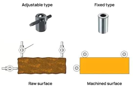
Typically, screw-type adjustable locators are used for positioning on the rough surface of the workpiece, while fixed-type locators (with workpiece contact surfaces that have been ground) are used for positioning on the machined surface of the workpiece.
2. Basic Principles of Part Hole Positioning
When using holes machined in previous operations of a part for positioning, it is necessary to use guide pins with tolerance.
Through the precise coordination of the workpiece hole and the external shape of the guide pin, and according to the adjustment tolerance, the positioning accuracy can meet the actual requirements.
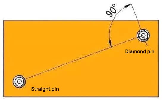
Additionally, when using dowel pins for positioning, it is common to use a straight pin and a diamond pin.
This configuration makes the assembly and disassembly of workpieces more convenient and rarely causes the workpiece to get stuck in the dowel pins.
Of course, it is also possible to use two straight dowel pins by adjusting the fitting tolerance. However, for more accurate positioning, the most effective method typically involves using a straight dowel pin and a diamond pin.
In situations employing a straight dowel pin and a diamond dowel pin, the alignment direction of the diamond dowel pin (where it contacts the workpiece) is generally at a 90° angle to the line connecting the dowel pin. straight guide and diamond pin.
This configuration is designed for angular positioning (direction of rotation of the part).
Relevant knowledge about clamps
1. Classification of forceps
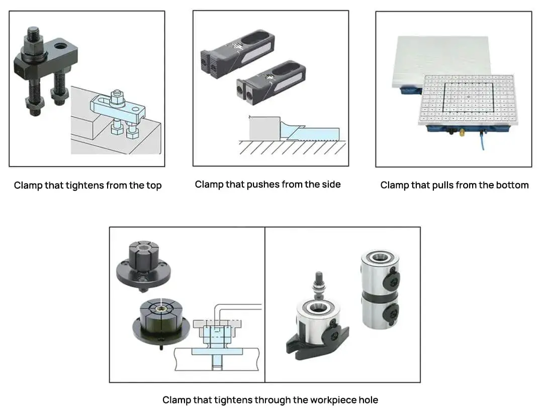
Based on the attachment direction, they are generally divided into the following categories:
Next, let's look at the features of various clamps.
1. Top-to-Bottom Clamps
Top-down clamps, which apply pressure from above the part, cause the least deformation during clamping and guarantee maximum stability during the machining process.
Therefore, in most cases, securing the part from above is the first consideration. The most common example of top-down clamping devices are manual mechanical clamps.
For example, the clamp shown below is known as a “maple leaf” clamp. Clamps consisting of a pressure plate, double-head screws, a bottle jack, and nuts are called “maple leaf” clamps.
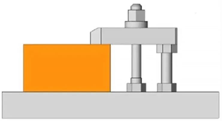
Furthermore, based on the shape of the workpiece, different shapes of pressing plates can be selected to match various workpiece configurations.
The relationship between the clamping torque and the clamping force of a pine needle clamp can be calculated through the screw driving force.
The simple calculation formula for clamping force is as follows:
F (kN) = T (N×m) / 0.2d
(where d refers to the nominal screw diameter).
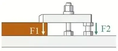
| T(N·m) | F(KN) | F1, F2(KN) | |
| M6 | 15 | 12.5 | 6.3 |
| M8 | 25 | 16.0 | 8.0 |
| M10 | 50 | 25.0 | 12.5 |
| M12 | 80 | 33.0 | 16.5 |
| M16 | 150 | 47.0 | 23.5 |
| M20 | 200 | 50.0 | 25.0 |
| M24 | 300 | 62.5 | 31.3 |
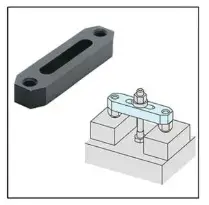
In addition to sheet clamps, there are other similar clamps that fix the workpiece from above.
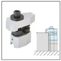
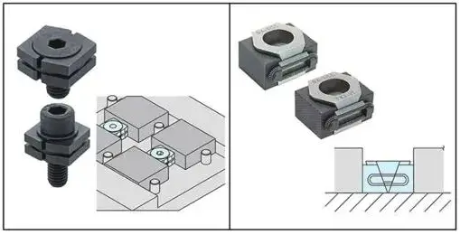
2. Side fixation device
Traditionally, clamping parts from above has been the most stable method, resulting in the lowest workload for the part.
However, when it is necessary to work on the top of the part, or when top fixing is not appropriate for various reasons, side fixing can be an alternative.
However, lateral clamping can produce an upward force on the workpiece. This force needs to be considered when designing the clamping device.
Clamps that are attached laterally, as shown above, generate a lateral force along with a downward diagonal force. This type of accessory effectively prevents the workpiece from lifting.
There are also other similar clamps that are attached to the side.
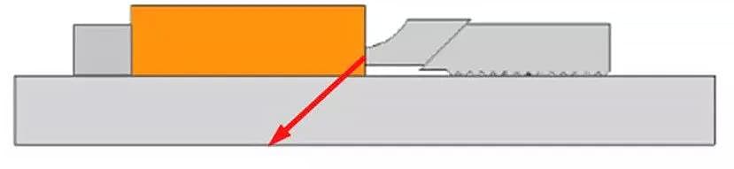
3. Using a pull-down clamp for workpieces
When machining surfaces of sheet metal parts, not only is it inappropriate to clamp from above, but the side pressure is also unreasonable. The only viable method is to employ a drop-down approach from below.
When pulling down from below, if the workpiece is made of iron, magnetic forceps are usually used. For metal parts other than iron, a vacuum suction cup is generally applied for pull-down fixing.
In both scenarios, the magnitude of the clamping force is directly proportional to the contact area between the workpiece and the magnet or vacuum cup.
If the machining load is too high when working on small parts, the results of the machining process may not be satisfactory.
Furthermore, when using magnets or vacuum suction cups, the contact surface with the magnet and suction cup needs to reach a certain level of smoothness for safe and normal operation.
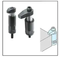
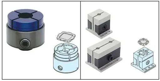
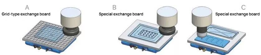
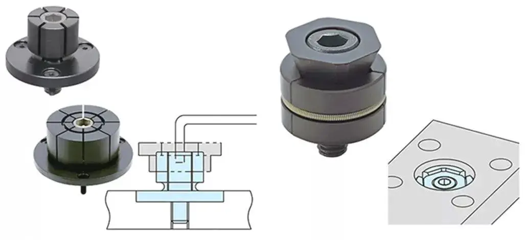
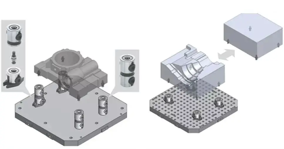
4. Using hole fixing devices
When performing multifaceted simultaneous machining or mold processing with a 5-axis machine, hole clamping is often chosen to avoid interference from clamps and tools.
Compared with clamping from the top or side of the workpiece, hole clamping places less load on the workpiece, effectively preventing its deformation.
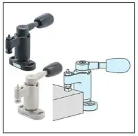
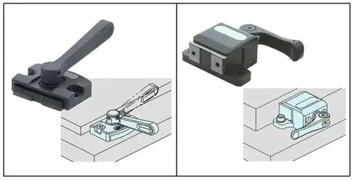
2. Pre-fixation
The text above mainly discusses part clamping devices and how to improve their operability. The use of pre-clamping is also crucial to improve operability.
When vertically positioning a workpiece on the base, the workpiece will fall due to gravity. At this point, you must simultaneously hold the part in place and operate the clamp.
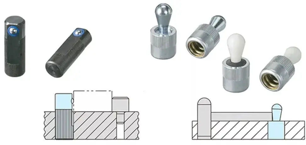
Operability decreases significantly and clamping time becomes longer when the workpiece has a substantial weight or when several parts are clamped simultaneously.
In these cases, the use of this type of spring-loaded pre-clamping product allows the operator to clamp the part while it remains stationary, significantly improving operability and reducing clamping time.
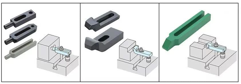
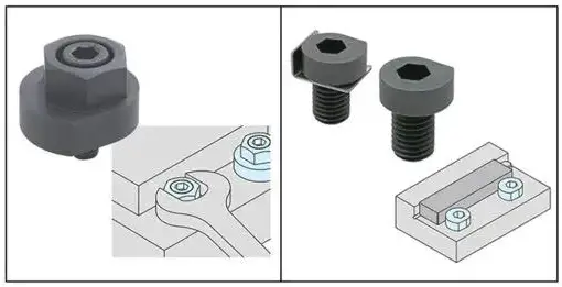
3. Considerations when choosing tweezers
When using multiple types of clamps on the same device, clamping and releasing tools must be standardized.
For example, as shown in the image below on the left, when using a variety of wrenches for clamping, the overall load on the operator increases and the total time for clamping the workpiece increases.
As illustrated in the image on the right below, the standardization of wrench and screw sizes makes the operator's task easier on site.

Furthermore, when setting up the clamps, the operational ease of clamping the part must be taken into account as much as possible. If the workpiece needs to be tilted for clamping, the operation will be inconvenient. Therefore, such situations should be avoided when designing the templates.