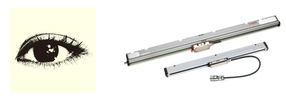
The grid ruler is a positioning detection element for the linear axis of CNC machine tools.
It acts as the “eyes” of a human operator, monitoring whether the linear axis moves accurately to the position required by the numerical control system after executing the NC program.
Without a grid ruler, the movement accuracy of the linear axis depends entirely on the accuracy of the NC system and the accuracy of the mechanical transmission.
After prolonged use of CNC machine tools, due to changes in electrical calibration parameters and increased mechanical errors, the linear axis may deviate significantly from the position required by the numerical control system program.
In this case, neither the control system nor the machine operators would be aware of this deviation. To accurately detect such problems, maintenance personnel need to perform precision tests on the machine tool.
Therefore, for CNC machine tools without a grid ruler, periodic accuracy testing is essential, otherwise it may result in excessive variations in machining accuracy or even scrap of the products being processed.
If a grid ruler were installed on the linear axis of a CNC machine tool, the mentioned problem would be solved without the need for human intervention.
The grid ruler acts as a position sensing element, and if the linear axis is unable to reach the precise position required by the numerical control system due to mechanical reasons, the grid ruler sends feedback to the NC system, allowing the linear axis accurately reach your position.
In this case, the grid ruler acts as an independent monitoring function, similar to the eyes of a human operator, continuously “watching” the position of the linear axis, ensuring that it reaches the position required by the numerical control system.
When producing new machine tools or rebuilding old ones, the purpose of using a grid ruler is to increase the accuracy of the linear axis.
However, the accuracy of this axis does not depend only on the grid ruler, but mainly on the precision of the mechanical geometry of the linear axis itself.
The grid ruler cannot replace the precision of the mechanical component; it just improves your performance.
Many people have misunderstandings about this issue, especially if the geometric accuracy of the machine tool's linear axis is low. For example, some lathes use a rack for transmission, which results in a large backlash.
Even when a grid ruler is used with such an axis, it may cause oscillations when approaching the precise position due to poor transmission accuracy.
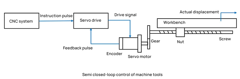
Semi-closed-loop control systems cannot control transmission errors caused by the machine tool transmission mechanism, thermal deformation errors produced by transmission mechanisms during high-speed operation, and errors caused by wear of transmission systems. transmission during high-speed operation.
During the machining process, these errors severely affected the machining accuracy and stability of CNC machine tools.
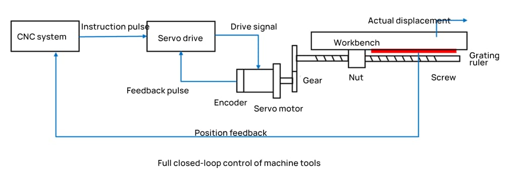
Grid rulers for linear axes achieve fully closed loop control of CNC machine tool linear coordinates, reducing the above-mentioned errors, improving positioning accuracy, repeatability accuracy and machine tool accuracy reliability.
As a key component to improve the positioning accuracy of CNC machine tools, the popularity of grid ruler is increasing among users.
CNC machine precision
The accuracy of CNC machine tools can be classified into three main aspects, including geometric accuracy, positioning accuracy and machining accuracy.
Geometric accuracy, also called mechanical accuracy, is the comprehensive geometric shape error of critical machine tool components after assembly.
The measuring tools and methods used to detect it are basically the same as those used in common machine tools, but with higher requirements.
Taking a typical vertical machining center as an example, its geometric accuracy includes the following parameters:
- 1. Flatness of the work table
- 2. Orthogonality of movement in different coordinate directions
- 3. Parallelism of the work table in relation to the directions of the X and Y coordinates
- 4. Spindle rotation accuracy
- 5. Parallelism of the spindle axis in relation to the direction of the Z coordinate in the movement of the main spindle box
- 6. Linearity of spindle movement in the Z coordinate direction
Positioning Accuracy
Positioning accuracy refers to the actual positioning accuracy that the main components of the machine tool can achieve at the end of the movement. The difference between the actual and desired position is known as positioning error.
In CNC machine tools, positioning accuracy is also called machine movement accuracy and is determined by the accuracy of the CNC system and the mechanical transmission error.
The movement of each component of the machine tool is completed under the control of the CNC device, and the precision that each component of the movement can achieve directly affects the accuracy of the machined part.
Therefore, positioning accuracy is a critical inspection item.
Repeatability Accuracy
Repeatability accuracy refers to the degree of consistency in position accuracy obtained by repeatedly executing the same program code on a CNC machine tool.
Repeatability accuracy is affected by factors such as servo system characteristics, backlash and stiffness of power transmission links, as well as friction characteristics.
In general, repeatability accuracy is subject to occasional errors in the normal distribution and affects the consistency of a batch of processed parts, making it an essential accuracy indicator.
Related Reading: Positioning Accuracy vs. Repeatability in CNC Machines
Machining precision
Machining accuracy is affected by several factors that are not fully reflected by geometric and positioning accuracy, which are typically detected without cutting load or with the machine tool in a stationary state or in slow motion.
For example, under the influence of cutting and clamping forces, machine tool components will undergo elastic deformation. Machine tool components will also undergo thermal deformation due to internal heat sources (such as overheated bearings and gears, etc.) and changes in ambient temperature.
Furthermore, the machine tool generates vibrations under the influence of cutting forces and movement speed. Furthermore, when the moving components of the machine tool move at working speeds, the accuracy of their movement differs from that measured at low speeds due to the oil film on the sliding surfaces and other factors.
All of these factors can cause changes in the static accuracy of the machine tool, affecting the machining accuracy of the part.
The accuracy of the machine tool under the influence of external loads, heating and vibrations during work is known as the dynamic accuracy of the machine tool.
Dynamic accuracy is closely related to static accuracy and largely depends on the rigidity, vibration resistance and thermal stability of the machine tool.
At present, the comprehensive dynamic accuracy of the machine tool is generally evaluated by the machining accuracy of the parts produced through cutting operations, which is known as the working accuracy of the machine tool. Working accuracy reflects the comprehensive influence of various factors on machining accuracy.
Methods to improve CNC machining accuracy
At present, there are mainly two methods to improve the machining accuracy of CNC machine tools in the parts machining industry: error prevention and error compensation.
Error prevention methods
Error prevention refers to measures taken to improve the quality level of component design, processing and assembly, effectively control environmental factors, and achieve the objective of eliminating or reducing sources of errors.
For example, the use of thermally symmetrical guide rails and high-rigidity ball screws for temperature control can effectively reduce the thermal deformation of the machine tool and the temperature rise of the heat source, thereby reducing the occurrence of errors.
Error prevention methods are mainly divided into three categories: size error, geometric error prevention, thermal deformation error prevention and other forms of error prevention.
These methods can reduce the probability of errors occurring to a certain extent, but it is almost impossible to completely eliminate thermal deformation and geometric errors.
Furthermore, the machining precision of the machine tool has a significant impact, and improving the quality of parts is costly, making it uncommon in practical applications.
Error compensation methods
Error compensation involves installing precision probes, position sensors, grid rulers and other equipment on CNC machine tools to provide feedback on the machine tool's machining errors in real time to the CNC system.
The machine tool automatically compensates for machining accuracy, improving the machining accuracy of parts and significantly reducing raw material costs.
Common failures of grid rulers as position detection elements on linear axes
1. Zero pulse cannot be found when the linear axis returns to the reference point.
In terms of performance, the shaft continues to rotate until it collides with the shaft limit during return to the reference point.
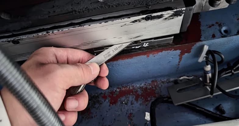
This failure is usually caused by dirt on the reading head or grid ruler. To solve this problem, remove the read head and clean it with anhydrous alcohol, and wipe the scaled part with a silk cloth dipped in anhydrous alcohol.
2. An alarm was triggered on the linear axis of the CNC machine tool during operation.
If the linear axis of a CNC machine produces an alarm during operation, the following alarms may appear depending on the control system used: “Hardware encoder error” for Siemens 840D or LNC systems, and “Feedback error” for Fanuc systems .
Reasons:
(1) Due to vibration or other reasons, the distance between the read head and the grid scale on the machine tool increases during use, causing the CNC system to incorrectly assume that the grid scale is defective.
To solve this problem, adjust the distance between the reading head and the grid scale according to the grid scale manual. The distance between the reading head and the scale body should be around 1-1.5 mm and not exceed 2 mm.
(2) Improper installation of the grid scale, such as installation near oil wells, may result in the scale being contaminated by oil and gas.
In this case, the “fixed scale” and “moving scale” of the grid scale must be cleaned separately, and then the grid scale must be adjusted and tested before use.
(3) Improper installation of the read head may damage the unit itself.
In a worst-case scenario, aluminum alloy debris can enter the fixed fingerboard of the scale, causing damage to the scale lines and permanently rendering the scale unusable.
3. The linear axis of the CNC machine tool went out of control abruptly.
In most cases, when the linear axis of the CNC machine tool goes out of control, it is due to the contamination of the position sensing element such as the grid ruler.
To solve the problem, the grid or reading head of the grid ruler needs to be thoroughly cleaned.

4. Other flaws:
After years of experience in CNC machine tool maintenance, we have observed that the grid ruler, as a position detection element of the CNC system, can improve the positioning accuracy of the linear axis of the machine tool when the mechanical part of the machine tool is operating smoothly.
Furthermore, the grid ruler can detect possible dangers or problems in the mechanical part of the machine tool.
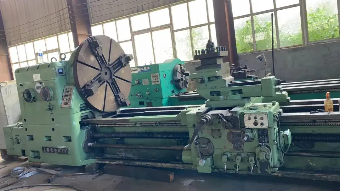
A C61200 lathe produced by Wuzhong Corporation was retrofitted with a FAGOR 8055TC CNC system.
During processing of a roll, which had an elliptical body, the X-axis moved away from the roll when the cutting tool encountered a relatively large area of the roll body in the absence of an X-axis movement instruction.
When the cutting tool touched a relatively small area of the roll body, the X-axis moved toward the roll, causing the X-axis to move back and forth. After inspection of the machine tool's CNC system, it was found that the X-axis AC servo motor was locked in the absence of an “enable” signal.
When the X-axis position sensing element was shielded and replaced with a semi-closed-loop system, the phenomenon of the X-axis moving back and forth disappeared during cutting.
Some people thought that this phenomenon was caused by problems with the grid ruler, but upon inspection, it was found that the rear cover of the X-axis ball screw was loose.
Therefore, when the roller was rotating, because the roller had an elliptical shape, when the cutting tool encountered a relatively large area of the roller body, the roller exerted an “upward push” force on the X axis, pushing the . axis away from the direction of the roll diameter.
At this time, the movement of the X axis was not caused by the numerical control instructions of the machine tool. The grid ruler used to detect the X-axis position detected that the X-axis moved in the “+X” direction (away from the roll body) without receiving any instructions from the CNC system.
The function of the grid ruler is to detect whether the linear axis moves accurately under the action of numerical control instructions. If the linear axis does not move accurately, the numerical control system intervenes to position the linear axis accurately.
Therefore, when the cutting tool touched a relatively small area of the roll body, the tool had a certain clearance with the roll body, and the grid ruler caused the X axis to move in the direction of the roll diameter to meet position in the X -axis coordinate position indicated by the numerical control system.
In this way, when the roller rotates a circle, the X axis moves alternately in the “direction away from the roller diameter” and in the “direction near the roller diameter” when there is no data instruction movement on the roller processing, the X axis moved back and forth due to the loose ball screw back cover.
When a linear axis of a CNC machine tool using a closed-loop system experiences motor tremors or oscillations, it is necessary to protect the position sensing element to eliminate the abnormal phenomenon.
Generally, first check the cleanliness of the position sensing element such as the grid ruler and reading head, and whether the installation position of the reading head is reasonable, and exclude factors that cause the position sensing element to malfunction.
If the position sensing element is working properly, there is likely a problem with the linear axis mechanical drive chain.
In this case, it is necessary to check whether there is any play in the components of the mechanical transmission chain, whether there is wear on the mechanical parts and whether the corresponding lubrication of the mechanical transmission chain is adequate.