I. Introduction to the problem
During the threading process on a CNC lathe, the following problems often arise:
(1) The threading tool is damaged in the middle of the process.
(2) There is a need to replace the threading tool for high-speed precision threading.
(3) After removing and measuring the thread, it is found that the depth is insufficient. We often feel helpless when encountering these problems because after changing the tool or reclamping the workpiece, it is difficult to align the threading tool with the original spiral groove and the starting position cannot be located accurately, leading to misalignment of the screw thread.

II. The principle of thread cutting on a CNC lathe
To solve these problems, we first need to understand the principle of threading on a CNC lathe. To perform threading, it is necessary to accurately ensure that, for each revolution of the part, the tool advances one step.
To achieve this, a spindle encoder is configured on the CNC lathe. Using its synchronous pulse as a control signal for the tool entry and exit points, a corresponding relationship is established between the number of feed servo motor pulses and the spindle speed.
However, as there is no direct mechanical connection between the spindle rotation and the feed movement in a CNC lathe, it is not easy to achieve cutting of the tool tip along the original spiral groove after reinstalling the tool or workpiece.
III. Existing prevention measures
Currently, most companies use a single clamping tool for threading on CNC lathes. Coarse and fine cuts are made with the same tool and at the same speed. If the tool breaks in the middle of the process, the tool shank will not be removed and the blade will be directly replaced to avoid thread misalignment.
However, if separate tools are used for coarse and fine cuts or if the workpiece is clamped again, this may lead to misalignment of the thread.
4. Solution to the problem
If the tool is damaged during threading or if it needs to be replaced with a precision threading tool, the new tool can be installed and simply realigned. During realignment, it is relatively easy to adjust in the X direction.
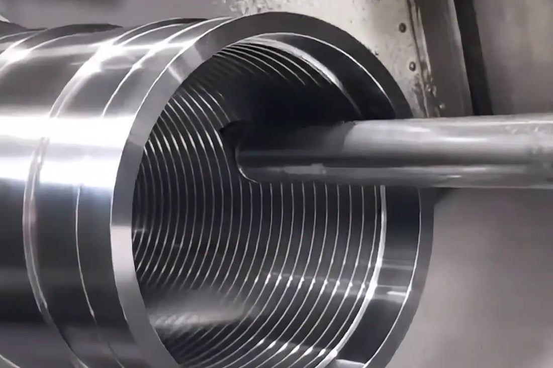
The key is alignment in the Z direction. Many people move the tool tip to the end face of the workpiece by feeling, as shown in Figure 1.
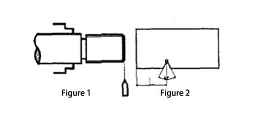
This method can lead to significant alignment errors, which may be acceptable for rough cuts but not for precision cuts.
Here, I introduce a method where you can use an existing angle template or a template made by yourself, as shown in Figure 2. The distance L in the figure can be measured accurately.
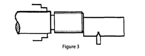
During the tool setup process, as shown in Figure 3, the template is placed on the end face of the part. The tool is then moved to the inner corner of the model. The Z axis tool offset L value is then entered into the system. This tool setting method is highly accurate and suitable for precision tool setting.
Single or small batch thread repair
If the threaded part is unloaded after turning and it is found that the thread depth is insufficient, it will be necessary to retighten for repair. This situation is quite problematic. The first issue to resolve is the runout problem after reassembling the part.
An open sleeve can be made to eliminate the deviation error; Most people probably know this method, so I won't go into details. The remaining issue is to ensure that the tool follows the original spiral groove during cutting to avoid thread accidents.
This problem is easily solved on common lathes, but is more challenging on CNC lathes. The method that many people use is shown in Figure 4.
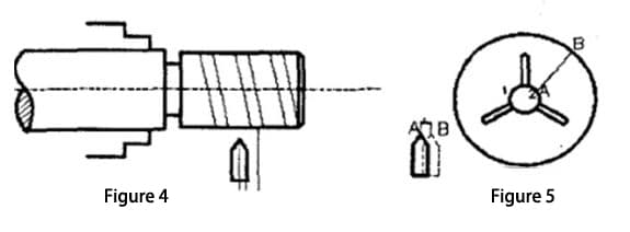
After setting up the tool, make sure it does not touch the part and run the raw thread program at slow speed.
Measure the distance L from the tool tip to the spiral groove, and then modify the thread cutting starting position in the repair program. Move it from the original point A by a distance L to point B. Repeat the above process and adjust the distance L. Continue this process until the tip of the tool cuts into the thread groove.
This method requires constant adjustments of the distance L and is time-consuming. In fact, we can slightly modify the original program to solve this problem. Just change the line length in the program to about 2 mm.
After clamping the workpiece and adjusting the tool, access the program. Turn a very shallow thread and find the starting position of the thread on the end face, as shown in Figure 5.
Assuming that the starting position of the newly turned thread is at point 2 and the original thread starts at point 1. Draw a line AB at point 2 of the chuck, and then loosen the chuck jaws. Rotate the piece from point 1 to point 2 along the AB mark line. If the workpiece moves axially during rotation, the thread tool must be reset in the z direction.
Clamp the workpiece and change the thread length in the program back to its original value. Run the program once to perform a test cut and check for errors. Adjust the starting position of thread cutting based on the error.
The thread cut from point 2 is too short and can be removed by chamfering. This repair method is faster and more accurate than the previous one, the main step being to accurately rotate the part from point 1 to point 2.
If a small batch of threaded parts needs repair, we can use the original program to make a new thread, find the starting position of the thread, draw a line on the chuck as a mark, and use the above method to repair.
Large batch thread repair
If a large batch of threaded parts needs repair, a quick, convenient and accurate method is needed. I summarized a method in practice for discussion.


