G00▲: Quick point positioning
G00 X__Z__
G01: Linear Interpolation
G01 X__Z__F__
G01: Chamfer or Fillet Command
G01 X(U) Z(W) C
G01 X(U) Z(W) R
The values of X (U) and Z (W) represent the coordinates of the hypothetical point of intersection between adjacent lines AD and DE within the part coordinate system, where the incremental coordinate values. The C value means the relative distance to the chamfer starting point. The R value denotes the radius of the fillet arc.
G02: Clockwise arc interpolation
G02X__Z__R__F__
G02X__Z__ E__K__ F__
R represents the radius of the arc. When the central angle of the arc varies from 0° to 180°, R assumes a positive value; for a central angle between 180° and 360°, R takes on a negative value. I and K denote the incremental coordinates of the center of the arc in relation to the X and Z axes of the starting point of the arc, that is, the center coordinates subtract the coordinates of the starting point (I is represented by the radius value). When I and K are zero, they can be omitted.
G03: Counterclockwise arc interpolation
G03 X__Z__R__F__
G03X__Z__ E__K__ F__
Identical to G02.
G04: Pause
G04X1.5; or G04 P1500; P without a comma.
G07.1 (G107): Cylindrical Interpolation
G07.1IPr (Effective); G07.1IP0 (Cancellation);
G10▲: Programmable data input
G10 P__X__ Z__R__ Q__
G11: Programmable data input cancellation
G12.1 (G112): Polar Coordinates Instruction
G13.1▲: Polar Coordinates Cancellation
G17: XY Plan Selection
G18▲: XZ Plane Selection
G19: YZ Plan Selection
G20: Inch Input
G21: Millimeter Input
G22: Enable stored course detection
G23: Disable stored course detection
G27: Reference point return check
G27 X(U) Z(W)
The tool is checked for its return to the designated X, Z coordinates as specified in the program using the G00 command. If the return is accurate, the indicator light comes on. However, discrepancies result in system alarms on the machine tool.
G28: Automatic Return to Reference Point
G28 X(U) Z(W); X and Z are the points passed during the return process.
G29: Return to reference point
G29 X(U) Z(W)
From the reference point through the midpoint to the specified X and Z positions, the midpoint is the point designated by G28, therefore this command can only appear after G28.
G30: Return to set point
G30 P2/P3/P4XZ
P2, P3, P4 represent the 2nd, 3rd and 4th reference points respectively, while X and Z are the intermediate points.
Meaning: The tool passes through the intermediate points to reach the positions of the 2nd, 3rd and 4th reference points.
G31: Skip function
G32: Equal pitch threading
G32X(U)_Z(W)_F_Q_
G32 Z(W)F; (Cylindrical thread)
G32X(U)F; (Final thread)
G32X(U)Z(W)F; (Conical thread)
Observation:
1. When programming, the input and output segments must be incorporated into the thread turning program.
2. For conical thread machining, when the angle α is less than or equal to 45 degrees, the thread pitch is specified in the direction of the Z axis; When the angle α is greater than 45 degrees and less than or equal to 90 degrees, the thread pitch is specified in the X-axis direction.
3. Q represents the initial angle of the thread, without a decimal point, and the unit is 0.001°.
G34: Variable Pitch Thread
G34 X(U) Z(W) FK ; (Conical thread)
K represents the increment (positive value) or decrement (negative value) of the step per revolution, the rest is equal to G32.
G36: Automatic X Tool Compensation
G36X
G37: Automatic Z Tool Compensation
G37Z
G40: Tip Radius Compensation Cancellation
G41: Left offset of tool nose radius
G41(G42)G01(G00)XZF
G40 G01(G00) XZF
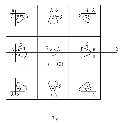
For the front tool holder, the outer circle is G42 with position number 3, and the hole is G41 with position number 2. The following figure shows the position number of the front tool holder, with positions 2 and 3, and 1 and 4 reversed on the rear tool holder, while the rest remains the same.
G42: Tool nose radius offset to the right
G50: Setting the coordinate system or maximum speed limit
G50 XZ or G50 S
G50.3: Presetting the part coordinate system
G50.2: Polygon rotation cancellation
G51: Polygon Turning
G52: Local coordinate system
G52 X20 Z20: The X\Z values represent the position of the origin of the local coordinate system within the original part coordinate system.
If G52 X0 Z0: cancels the local coordinate system, restoring the original origin of the coordinate system.
G53: Machine tool coordinate system selection
Deselect the workpiece coordinate system and choose the machine tool coordinate system.
(G90) G53 X_ Y_ Z_: valid in absolute command (G90), but invalid in incremental command (G91).
Observation:
(1) Tool diameter compensation, tool length compensation and tool position correction must be canceled before assigning their G53 command. Otherwise, the machine tool will move according to the assigned offset values.
(2) Before executing the G53 command, manually or through the G28 command, return the machine tool to the origin. This is because the machine tool coordinate system must be defined before issuing the G53 command.
G54▲: Selection of the coordinate system for part 1
G54; On by default.
G55-59: Selection of part coordinate systems 2-6
G65: Non-modal macro program call
Class A uses the FANUC 0TD system, while Class B uses the FANUC 0I system.
Local variables are #1-#33, shared variables are #100-#149, #500-#549, and system variables are #1000 and higher.
Macro programs end with M99 and can be invoked with M98 or “G65 P(program number)L(count)”.
The format for Class A programs is: G65 H(a)P(b)Q(c)R(d), where a is the H code, b is the result variable and c, d are two operation variables.
Class B macro program operation command.
| Assignment | #eu=#j | Floor function | #i=FUP(#j) |
| Addition | #i=#j+#k | Natural logarithm | #i=LN(#j) |
| Subtraction | #i=#j-#k | Exponential function | #i=EXP(#j) |
| Multiplication | #eu=#j*#k | Or | #iOU#j |
| Division | #i=#j/#k | Exclusive or | #iXOR#j |
| Sine | #i=SIN(#j) | AND | #iAND#j |
| Inverse Sine | #i=ASIN(#j) | BCD to BIN Conversion | #i=BIN(#j) |
| Cosine | #i=CON(#j) | BIN to BCD Conversion | #i=BCD(#j) |
| Inverse Cosine | #i=ACON(#j) | It's the same as | equalization |
| Tangent | #i=TAN(#j) | It is not equal to | HUH |
| Inverse Tangent | #i=ATAN(#j)/(#k) | Bigger then | GT |
| Square root | #i=SQUARE(#j) | Better than or equal to | GE |
| Absolute value | #i=ABS(#j) | Less than | LT |
| Rounding | #i=ROUND(#j) | Less than or equal to | LE |
| Roof | #i=FIX(#j) |
Control command: GOTO n – Unconditional jump
IF (condition expression) GOTO n – conditional jump instruction
WHILE (condition expression) DO m (m=1, 2, 3…) – Loop command
…
END m;
G66: Macro Program Modal Invocation
G67: Macro Program Modal Invocation Cancellation
G70: Internal and External Cylindrical Fine Turning Compound Canned Cycle
Programming format: G70 P(ns) Q(nf)
Where:
- ns represents the segment number of the initial program of the precision machining process;
- nf means the number of the final segment of the precision machining process program;
Grades:
(1) The G70 command cannot be used independently; must be combined with the commands G71, G72, G73 to complete the precision machining canned cycle, that is, after rough turning of the part with the commands G71, G72, G73, G70 is used to specify the turning canned cycle precision by removing the tolerance left by rough machining.
(2) In this case, the F, S, T commands in program segments G71, G72, G73 are invalid; only F, S, T in ns~nf program segments are effective. When the F, S, T commands are not specified in the ns~nf program segments, the F, S, T of the rough turning cycle are effective.
G71: Internal and External Cylindrical Fine Turning Compound Canned Cycle
Programming Format: G71U (△d) R(e);
G71 P(ns) Q(nf) U (△u) W(△w) FST ;
Where:
- ns: Refers to the initial program number of the precision machining segment;
- nf: Refers to the final program number of the precision machining segment;
- △u: Represents the remaining tolerance for precision machining in the radial direction (X-axis direction) (diameter value);
- △w: Represents the remaining tolerance for precision machining in the axial direction (Z axis direction);
- △d: Represents the cutting depth per time (radius value);
- and is the amount of radial retraction during tool retraction
- F: Represents the feed speed during rough machining; S: Represents the spindle speed during rough machining;
- T: Represents the tool number used during rough machining.Notes:
(1) When the above instruction is used for machining the inner contour of the workpiece, △u should be a negative value.
(2) When using G71 for roughing, only the functions F, S, T included in program segment G71 are effective. The functions F, S, T included in the ns~nf program segment are ineffective for the roughing cycle, even if they are specified. Tool compensation can be performed and tool tip radius compensation can be programmed before G70, usually incorporated into the movement approaching the starting point. For example: G42G00X55Z2; G70P10Q20; G40G00X100Z50;
(3) This instruction is applicable where there is a monotonic increase or decrease in the Z coordinate, and the X coordinate also changes monotonically. Program segment Ns should advance along the X axis and Z values should not appear.
G72: End Face Rough Turning Compound Canned Cycle
Programming format: G72W (△d) R(e);
G72 P(ns) Q(nf) U (△u) W(△w) FST ;
2. d: Amount of retraction in the Z direction, without sign; other parameters are the same as G71. Program segment Ns must feed in the Z direction and cannot contain an X value. When the above command is used for internal contour machining of the part, △u must be a negative value.
Example: As shown in the figure, your program list is:
- O4534;
- N10 G50 X100.0 Z100.0;
- N20 M03 S1000;
- N30 G00 X100.0 Z5.0 M08;
- N35 G72W3R0.5
- N40 G72 P50 Q120 U0.5 W0.2 D3.0 F300;
- N50 G00 Z-60.0;
- N60 G01 Z-55.0 F200;
- N70X70.0;
- N80 X50.0 Z-35.0;
- N90 W15.0;
- N100X30;
- N110X20.0 W10.0;
- N120 Z5.0;
- N130 G00 X100.0 Z100.0 M09;
- N140 M05;
- N150 M30;
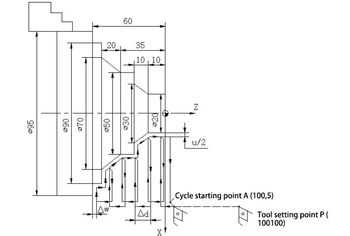
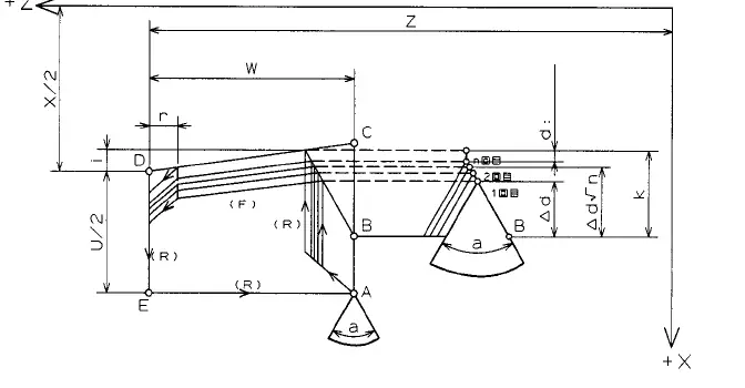
G73: Contour duplication cycle
Programming Format: G73 U(△i) W(△k) R (d);
G73 P(ns) Q(nf) U (△u) W(△w) FST ;
d: Represents the number of cycles in rough turning (layer count);
△i: During rough turning, the total tolerance to be removed in the X-axis direction (tool withdrawal amount) and direction, radius value. In other words: the raw size minus the smallest size of the part divided by 2. The hole is a negative value.
△k: During rough turning, the total tolerance to be removed in the Z axis direction (tool withdrawal amount) and direction; △k is usually zero. The rest is the same as the G71 command.
G74: Grooving Cycle/Drilling Cycle
G75: Radial Groove Cycle
Programming Format: G75R(e);
G75 X (U) Z(W) P(Δi) Q(Δk) R (d)F;
- e: Tool retraction distance;
- X (U) Z(W): End coordinates of the groove;
- Δi: Depth of each cut in the X direction, expressed as an unsigned radius;
- Δk: Change in Z direction after the tool completes a radial cut, without signal.
- D: Tool retract distance in Z direction when cutting bottom, generally omitted.
- F: Cutting feed speed.
Observation:
1. The final depth and final displacement of the Z direction are calculated by the system itself.
2. Δi, Δk are the minimum programming units, for example, P1500 means 1.5mm cutting depth.
G76: Compound Cycle for Thread Cutting
G76 P(m)(r) (α) Q(△d min) R(d)
G76 X(U) Z(W) R(i) P(k) Q(△d) F(L)
- m — The number of precision machining repetitions can be between 1 and 99, this is a modal value.
- r — Amount of chamfer at the end of the thread (the oblique withdrawal distance of the tool in the Z direction), is from 0.0 to 9.9 times the thread pitch, the unit is 0.1S, represented by two digits of 00 to 99.
- α — Thread tip angle (thread tooth angle), you can select one of the following six options: 80°, 60°, 55°, 30°, 29° and 0°, determined by two digits. This is a modal value.
- △d min — Minimum amount of tool return during cutting, specified as a radius value, in micrometers, with no decimal.
- d — Precision machining tolerance, represented as a modal value with decimal value of the radius, in millimeters.
- i — The difference in radius between the starting and ending points of the thread. When i is zero, it indicates standard straight thread cutting.
- k — Thread depth. For external threads, k is calculated as 649.5P, for internal threads, k is calculated as 541.3P, specified as a radius value in micrometers, with no decimal.
- △d — The first depth of cut, specified as a radius value, in micrometers, with no decimal.
- X, Z — In absolute value programming, they represent the coordinates of the thread end point under the part coordinate system. In incremental programming, they represent the values of the incremental coordinates of the cutting end point in relation to the starting point of the cycle, represented by U and W.
- L — Thread pitch, in millimeters.
G90: Cylindrical/Conical Surface Single Canned Cycle
G90 X(U) Z(W) RF;
R indicates half the difference between the X coordinate at the starting point and the X coordinate at the end point of cutting the conical surface. It can be negative, where negative indicates a regular cone and positive indicates an inverted cone. Without R, it is cylindrical cutting. Cutting speed: G00 – G01 – G01 – G00.
G92: Thread cutting cycle
G92 X(U) Z(W)FR;
R = (X starting point – X ending point) / 2. R is non-modal and must be included in all sentences.
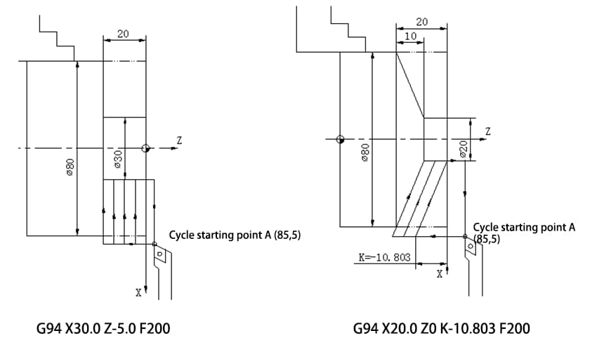
G94: End face cutting cycle
Command format: G94 X(U) Z(W) F;
Tapered End Face Cutting Command Format: G94 X(U) Z(W) KF
Where, X, Z represent the absolute value of the coordinate of the end point of the cutting segment;
U, W represent the value of the coordinate increment of the end point of the cutting segment in relation to the start point of the cycle; F represents the feed rate. K represents the difference in Z coordinate values between the start and end points of the cutting segment (usually a negative value), i.e. K=start point Z – end point Z.
G96: Execution with constant linear speed
M3S300; Initial speed
G50S1000; Maximum speed limit 1000
G96S100; Spindle speed 100m/min
…
G97▲: Constant linear speed cancellation, speed termination.
G97 S300; Constant linear speed cancellation, the speed is 300r/min
G98: Feed per minute
Unit: mm/min Example: G98 G01 X20 F200
G99▲: Feed per rotation
Unit: mm/rev Example: G99 G01 X20 F0.2;
M00: All actions stop.
M01: Program selection stop
You must press: Select stop key for it to take effect, equivalent to M00;
M02: Program termination
The cursor does not return.
M03/M04: Spindle forward (clockwise) / reverse (counterclockwise)
M03 S300;
M05: Spindle stop
M08/09: Refrigerant on/off
M30: Program termination
The cursor returns to the beginning of the program.
M98: subroutine invocation
Programming format: M98 PxxxxL;
or M98 Pxxxxxxx;
M99: Return to the main program
In this, the four digits after the P address after the call represent the subroutine number, the call after the L address represents the call times. When the call time is 1, it can be omitted, and the allowed repeat call time is up to 999. When the eight digits follow the P address, the first four represent the call times and the last four represent the sub number. -routine. When the call time is 1, it can be omitted.
If M99 P100; represents the return to program segment N100 of the main program, if the subroutine executes M99 L2, it means that the subroutine is forced to execute twice, regardless of how many times the main program requests it.
T××××: Tool command
In T0101, the first two digits represent the tool number, while the last two digits indicate the tool offset number.