1. Question
What methods are available to calculate cutting conditions for end milling?
In preparation for end milling, I consulted the cutting conditions table, but could not find the corresponding conditions for the desired machining.
What is the calculation method for milling conditions?
2. Response
The spindle speed is calculated based on the milling speed; feed is calculated based on feed per tooth; the cutting depth is derived from the cutter diameter.
The spindle speed is calculated from the cutting speed and the diameter of the cutter, with the cutting speed being referenced in the table of cutting conditions or machinability index.
The feed rate is calculated based on the feed per tooth, the spindle speed, and the number of teeth on the cutter. The cutting depth is derived from the cutter diameter. Perform machining tests based on the calculated results to adjust the milling conditions.
Method for calculating spindle speed
Formula to calculate rotational speed:
N=(1000*Vc)/π*Dc
Formula to calculate milling speed:
Vc=(π*Dc*N)/1000
- N: Revolutions per minute (min -1 )
- Vc: Milling speed (m/min)
- Dc: Cutting diameter (mm)
I. When the diameter of the tool used is not recorded in the cutting conditions table
You must calculate the milling speed based on the milling conditions of the nearest diameter using the formula provided. Then calculate the rotation speed. A more direct approach is to use the desired diameter as a reference and calculate the rotational speed by multiplying it by the ratio of the diameters.
Figure 2 Cutting conditions table
| Material to be machined
Milling conditions Cutter diameter (D) |
Mechanical Structural Carbon Steel (S45C-S55C) |
Alloy Tool Steel (SKD, SCM, SUS) |
Quenched and tempered steel (35-40HRC) (HPM, NAK) |
copper alloy aluminum alloy |
||||||||
| Feed rate (mm/min) | Rotation speed (minimum -1 ) |
Feed rate (mm/min) | Rotation speed (minimum -1 ) |
Feed rate (mm/min) | Rotation speed (minimum -1 ) |
Feed rate (mm/min) | Rotation speed (minimum -1 ) |
|||||
| Carving | Sideways | Carving | Sideways | Carving | Sideways | Carving | Sideways | |||||
| two | 140 | 270 | 10,190 | 90 | 190 | 7,350 | 70 | 150 | 6,620 | 330 | 650 | 25,200 |
| 2.5 | 170 | 340 | 8,610 | 90 | 190 | 6,410 | 70 | 150 | 5,570 | 370 | 740 | 21,000 |
| 3 | 180 | 360 | 7,250 | 110 | 210 | 5,570 | 80 | 160 | 4,620 | 420 | 840 | 16,800 |
| 3.5 | 200 | 400 | 6,300 | 130 | 250 | 4,830 | 80 | 170 | 3,990 | 440 | 880 | 14,700 |
For example, when calculating the rotational speed of an end mill with a blade diameter of 2.8 for machining structural carbon steel,
The rotational speed of an end mill with a blade diameter of 3 is 7250 (min -1 ),
Therefore, the rotational speed of an end mill with a blade diameter of 2.8 is: 7,250(min -1 )×3/2.8= approximately 7,768(min -1 ).
*Under constant milling speed, the smaller the blade diameter, the higher the rotation speed.
2. When the material to be machined is not listed in the cutting conditions table,
It is calculated by multiplying the rotation speed of other listed machined materials by the ratio of the machinability index between the materials to be cut.
For example, when calculating the rotational speed of an end mill with blade diameter 3 for machining gray cast iron,
The rotation speed when the blade diameter is 3 and machining structural carbon steel is 7,250 (min. -1 ).
When the machinability index of structural carbon steel is 70 and that of gray cast iron is 85,
The rotational speed when milling gray cast iron is: 7,250(min -1 )×85/70= approximately 8,804(min -1 ).
※The machinability index is a value that expresses the ease of machining materials, with the machinability of free-cutting steel set to 100. The lower the value, the more difficult it is to machine and can serve as a reference when setting the cutting speed .
Key points for setting rotation speed
【When using a ball end mill】
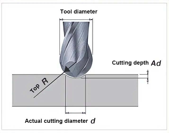
When using a ball end mill, the calculation based on the actual cutting diameter will be closer to actual machining conditions.
Figure 3 Method for calculating the actual cutting diameter and correct rotation speed
1. When spindle speed is limited
If the spindle speed is limited by the machine tool, resulting in a slower processing speed than specified in the cutting conditions table, the feed rate must be reduced accordingly.
For example, if the recommended cutting conditions are a spindle speed of 30,000 (min. -1 ) and a feed rate of 600 (mm/min), and the machine tool speed limit is 20,000 (min. - 1 ), then the feed rate will drop to 600 x 20,000 / 30,000 = 400 (mm/min). Furthermore, cutting speed can be maintained despite reduced spindle speed by increasing the cutter diameter.
2. When vibration measures are taken
Even when the spindle speed is reduced to avoid vibration and extend tool life, the change in cutting resistance within the common cutting speed range (e.g., 50~150 (m/min) for carbon steel used in machine structures) is minimal and does not increase efficiency.
Adjusting the cutting depth and feed rate is more effective. However, if vibration occurs at the inherent speed due to aging of the machine tool or if the part is machined without knowing the correct cutting speed, the spindle speed must be adjusted.
Feed rate calculation
The formula for calculating the feed rate is:
F=fz*N*Zn
The calculation formula for each cutting depth is as follows:
Fz=F/(Zn*N)
- F: Feed rate (mm/min)
- fz: Feed per tooth (mm/tooth)
- N: Spindle speed (min. -1 )
- Zn: Number of teeth
1. When the Cutting Conditions Table does not list the corresponding conditions for the tool cutting edge diameter:
When calculating with the chip load per tooth as constant, the chip load per tooth should be calculated based on the speed and feed of the nearest cutting edge diameter, and then the feed rate should be calculated using this value along with the machining speed.
In real applications, changes in the diameter and length of the cutting edge will affect the stiffness of the tool. This must be taken into account when calculating the chip load per tooth. For basic use, calculations can also be made based on the median values of the parameters listed in the Cutting Conditions Table.
Figure 5: Cutting Conditions Table
| Material to be machined
Milling conditions Cutter diameter (D) |
Mechanical Structural Carbon Steel (S45C | Alloy tool steel (SKD, SCM, SUS) | 40HRC) (HPM, NAK) | Copper alloy·Aluminum alloy | ||||||||
| Feed rate (mm/min) | Rotation speed (minimum -1 ) |
Feed rate (mm/min) | Rotation speed (minimum -1 ) |
Feed rate (mm/min) | Rotation speed (minimum -1 ) |
Feed rate (mm/min) | Rotation speed (minimum -1 ) |
|||||
| Carving | Sideways | Carving | Sideways | Carving | Sideways | Carving | Sideways | |||||
| two | 140 | 270 | 10,190 | 90 | 190 | 7,350 | 70 | 150 | 6,620 | 330 | 650 | 25,200 |
| 2.5 | 170 | 340 | 8,610 | 90 | 190 | 6,410 | 70 | 150 | 5,570 | 370 | 740 | 21,000 |
| 3 | 180 | 360 | 7,250 | 110 | 210 | 5,570 | 80 | 160 | 4,620 | 420 | 840 | 16,800 |
| 3.5 | 200 | 400 | 6,300 | 130 | 250 | 4,830 | 80 | 170 | 3,990 | 440 | 880 | 14,700 |
For example, when using a vertical cutter with a blade diameter of 2.8 to process structural carbon steel, we will calculate the feed rate of the vertical cutter as follows:
Given that the feed speed is 360 mm/min when the blade diameter is 3 and 340 mm/min when the blade diameter is 2.5, the feed speed when the blade diameter is 2.8 would be : (360-340) / (3-2.5 ) * (2.8-2.5) + 340, which is approximately 352 mm/min. Spindle speed is calculated using the “Spindle Speed Calculation Method”.
2. When the part material is not listed in the cutting conditions table:
The feed speed for the unlisted part material is calculated by multiplying the feed speed of another listed part material by the ratio of the machinability index between the two materials.
For example, when calculating the feed speed of a vertical milling cutter with blade diameter 3 when machining gray cast iron, the feed speed when machining structural carbon steel is 360 mm/min. The machinability index of structural carbon steel is 70 and that of gray cast iron is 85.
Therefore, the feed speed when milling gray cast iron is: 360(mm/min) * 85/70 = 437(mm/min). Spindle speed is calculated using the “Spindle Speed Calculation Method”.
Key points for setting feed speed:
1. When taking vibration prevention measures:
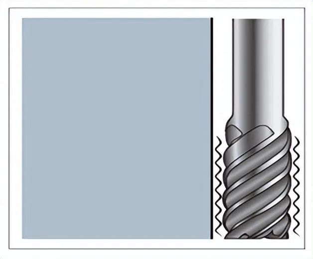
For vertical cutters with long blade lengths that are prone to vibration, or those with long necks and large projections, or thin blade diameter types, reducing the depth of cut or feed per tooth can proportionally decrease cutting resistance. Therefore, this is more effective than reducing spindle speed.
Figure 6 shows a schematic diagram of cutting with a vertical long-neck cutter.
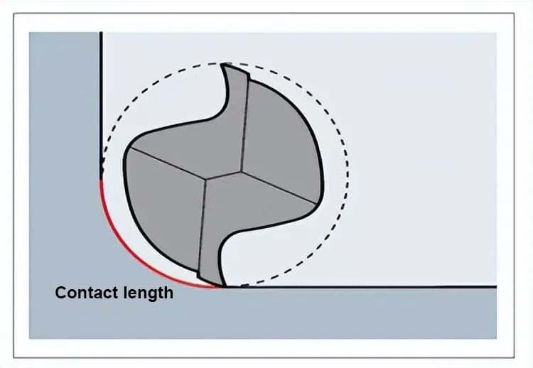
Furthermore, when machining corner areas in side processing, the contact length of the cutting edge increases, and measures are needed to reduce the feed rate.
Too little feed per tooth can accelerate wear. Except for end mills with a fine diameter (less than 2), the feed per tooth should not be less than 0.01 mm.
Figure 7: Schematic diagram of machining corner areas
Calculating Feed Rate
1. When using an end mill
Figure 8: Cutting conditions for an end mill
| Cutter diameter D | Ads | Ads | Road | |
| Groove | Side face | |||
| D<1 | ≤0.02D | ≤1.5D | ≤0.05D | |
| 1≤D<3 | ≤0.05D | ≤0.07D | ||
| 3≤D<6 | ≤0.15D | ≤0.10 | ||
| 6≤D | ≤0.2D | ≤0.15D | ||
Figure 9: Cutting Depth in Side Machining
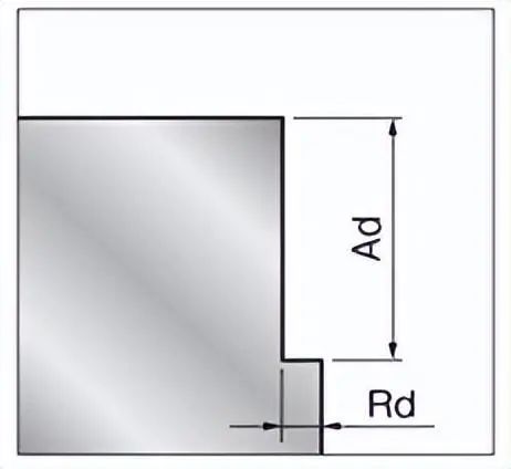
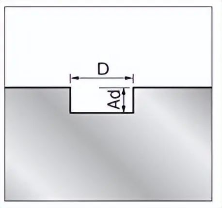
Figure 10: Cutting depth in grooving
The feed amount Ad and Rd are calculated by multiplying the cutter diameter by the coefficient in the cutting conditions table. For example, when the cutter diameter is 5 and side milling is being performed, according to the cutting conditions table, Ad is 1.5D and Rd is 0.1D. Therefore, Ad is 1.5×5, which is less than or equal to 7.5(mm), and Rd is 0.1×5, which is less than or equal to 0.5(mm).
2. When using a ball end mill
Table 11 (a) Cutting conditions for ball end mill
| Processing Content | Ads | Federal Police |
| Rough Machining | ≤0.1D | ≤0.3D |
| Precision Machining | ≤0.05D | ≤0.05D |
Table 12 (b) – Cutting conditions for ball end mills
| Upper end R | Material being machined | Quenched and tempered steel (35~40HRC) (HPM, NAK) | |||
| Milling conditions | |||||
| Effective length | Announcement(mm) | Pf(mm) | Cutting speed (mm/min) | Rotation speed(min-1) | |
| 0.1 | 0.5 | 0.01 | 0.01 | 340 | 50,400 |
| 1 | 0.01 | 0.01 | 300 | 50,400 | |
| 1.2 | 0.01 | 0.01 | 230 | 49,350 | |
| 0.15 | 1 | 0.01 | 0.01 | 500 | 50,400 |
| two | 0.01 | 0.01 | 390 | 45,150 | |
| 0.2 | 1 | 0.02 | 0.04 | 690 | 50,400 |
| two | 0.02 | 0.03 | 620 | 50,400 | |
| 3 | 0.01 | 0.01 | 440 | 43,050 | |
| 4 | 0.01 | 0.01 | 420 | 39,900 | |
Figure 13 shows the cutting depth Ad when using a ball end mill.
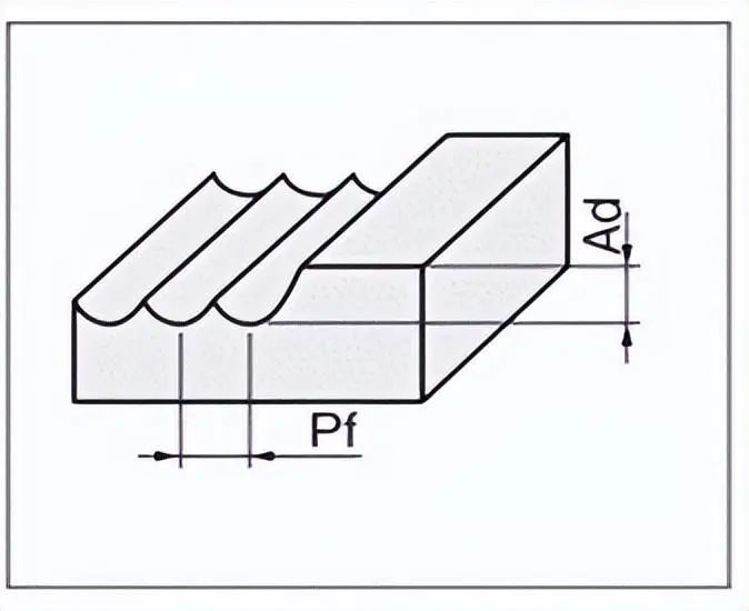
(a) When using a spherical end mill, the cutting depth Ad is calculated by multiplying the tool diameter by a given coefficient. For example, when the tool diameter is 2 and Ad is 0.1D, the calculation is 0.1 x 2 = 0.2(mm).
(b) When using the cutting conditions table for spherical end mills, the depth of cut Ad is read directly from the table. If the cutting conditions for the tool you want to use are not listed in the table, use the average value of the tool's closest diameter and effective length.
3. When the material to be machined is not listed in the cutting conditions table
Use the mechanical structural carbon steel or hardened steel listed in the cutting conditions table as a baseline.
For materials softer than the baseline, temporarily set the depth of cut to the same value and increase it to a level where problems will not occur during test machining.
For harder materials, set the value for the depth of cut multiplied by the ratio of the machinability index of the two and perform the test machining.