CAD Tut 3.
Use of status bar and visual reference – Ortho, Snap, Grid, Polar Tracking
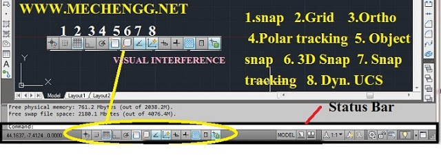 Visual Interference Toolbar
The GRID option creates a pattern of lines that spans an area of the screen. Using the grid is similar to placing a sheet of graph paper under a drawing. The grid helps you align objects and visualize the distance between them. The grid is not displayed in the plotted drawing. The default grid spacing, which means the distance between two lines on the screen, is 0.5 inches. We can see that the horizontal line sketched in the sketch is about 4.5 inches long. ORTHO – Orthogonal drawing or rectangular drawing, it means that when you rotate this feature, the lines you drag the mouse will be angled in relation to the UCS and you will only be able to draw the angle that is defined and is 90 degrees.
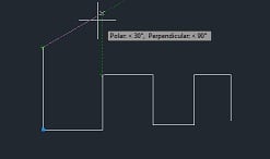 ortho uses polar tracking
POLAR – The polar coordinates follow when you draw the line, if this function is activated Ortho will be automatically turned off because when you draw with the POLAR function of the mouse you can draw lines at an angle to the set and you can also set it and draw you with absolute or relative coordinates when drawing lines
OSNAP – Aim (target) at a specific point on a line derived from the activated Osnap that contains some basic positions on the line, circle, image and the like. End point, midpoint and other crosshairs for other fixation points only appear when we activate Osnap mode (and activate each target). All figure lines, circles, etc. have a connection point to the target, in order to distinguish the GRIP (grips) from the target.
OSNAP mod: F3 => End Point, Midpoint, Center, Node, Quadrant, Intersection, Extension
OTRACK – F11 – Intersection, Perpendicular, Tangent, Nearest, Apparent intersection, Parallel
If you activate OTRACK/POLAR mode, you will have an extra active dashed line that helps you draw the line to align with a line (dot) to the already drawn parts of the drawings.
To configure the above feature:
1) Right-click the polar tracking icon (visual clutter toolbar) and click Configuration
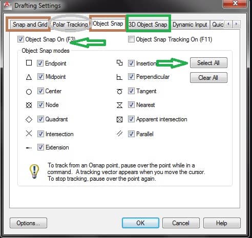 Snap, Polar Tracking, Object Snap Setting
Function Key – Tips:
Using the function key increases your drawing speed.
Ex.- When drawing, when you want to turn the osnap on or off, just press the F3 function key. Pressing osnap in the status bar is also the same.
Also,
F2 – Drawing/Text Window
F8 – Ortho on/off
F3 – Osnap on/off
F9 – On/Off
F6 – Coordinates activated/deactivated
F10 – Polar on/off
F7 – Grid on/off
F11 – Enable/disable object snap tracking