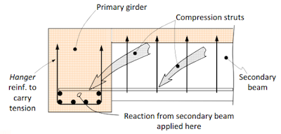
Suspended Shear Rebars
Suspension rods must be provided in the concrete beams that support the secondary beams.
Reinforcement should be provided at the main beam and placed around the connection of the two beams.
The final images show the reinforcement detailing method.
Design technique
We generally use primary beams to support secondary beams.
The reaction of the secondary rays is driven by the primary ray.
We usually design the primary beams with the reaction of the secondary beams in mind, and many times many engineers neglect the design at the joint.
The connection must be designed to accommodate secondary carrier reaction.
In the joint area we install suspension reinforcement in addition to the normal shear reinforcement.
Providing supporting reinforcement can avoid when the shear force at the edge of the main beam is less than 3(√f'c)b w2 D 2 since the formation of oblique cracks at this shear point is not yet fully developed.
Here b w2 is the width of the secondary beam and D 2 is the effective depth of the secondary beam.
The design method and detailing follow ACI guidelines.
The depth of the primary and secondary beams is h1 and h2, respectively. H b is the vertical distance between the bottom of the primary beam and the bottom of the secondary beam.
ϕA H F yes ≥ (1-h b /H 1 )V u2
Where,
ϕ = 0.75
A H = Area of suspension reinforcement close to one side of the support beam
F sim = yield strength of the reinforcement
v u2 = shear force considered at the end of the support beam
Project example
- Shear force included at the end of the support beam = 200 kN
- Yield resistance = 460 N/mm 2
- Girder beam height 600 mm
- Secondary beam height 400 mm
H b = 600 – 400 = 200 mm
Form the above equation,
0.75x460xA H ≥ (1-200/600) (2x200x1000)
A H ≥773 mm 2
Provide four 12mm rods
Existing reinforcement area = 113x2x4 = 904 mm 2
Four links are enough.
There are also some other methods for designing suspension stiffeners. The book “Design of Concrete Structures” by Arthur H. Nilson, David Darwin and Charles W. Dolan also contains a method for calculating reinforcement needs.
They suggested using the beam height ratio to calculate the required shear force.
v D = (h secondary /H primary ) (shear force)
For this cutting force we can find suspension reinforcements. Using the same concept as above, we can write the gain range as follows.
ϕA H F yes ≥V D
This allows us to find the support reinforcements.
Click here for more information on scissor construction.
Beam Shear Design to BS 8110
Dimensioning when cutting beams according to Eurocode 2

