This article explains the construction of a single angle section for tensile loading according to Eurocode 3. The construction of the angle section is simpler than the construction of a pressure element.
This article explains the design process and a practical example to help you understand the concept and design process.
Let's discuss design procedures
- Evaluate material properties
Depending on the thickness of the sheet and the type of steel, the yield strength (f j ) and breaking strength (f Ela ) can be found in Table 3.1 of Eurocode 3.
Then you get the γ m0 and γ m2 from section 6.1. These values may change according to national annexes.
- Calculation of design plastic load capacity – design tensile load capacity, N Pl, Rd
N pl, Rd = Af j /γ m0
- Calculate N u, Rd
N you, Rd can be calculated for angular sections connected in a leg by bolts from clause 3.10.3 (2) of EN 1993 – 1-8 as mentioned in clause 6.2.3 (5).
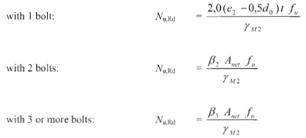
Depending on the number of bolts, there are three equations to calculate load capacity. For the angular section associated with a single screw, the following equation can be used.
N u, Rd = 2(e 2 -0.5 days 0 )tf Ela /γ M2 – For single bolts based on the number of bolts, select the appropriate equation.
If the number of screws is greater than one, the network must be taken into account in the calculation.

If there is an equiangular section, the net is the reduction of the bolt area relative to the gross cross-sectional area. However, the method is different for unequal angles.
-
- If the threaded connection is on the larger leg, the net is the reduction of the bolt area to the gross cross-sectional area.
- If the bolt connection is on the smaller leg, the net is the reduction of the bolt area from the corresponding cross-sectional area. For example, consider a section of 100 x 75 x 10. For a bolted connection on a 75 mm leg, the cross-sectional area should be taken as an angular section of 75 x 75 x 10.

Other equations from EN 1993-1-8, paragraph 3.10.3 (2), could also be used.
- Find t,Rd (design tensile strength) the minimum of N pl, Rd in u, Rd
- Check if N Ed. /N t, R ≤ 1.
Worked example: Checking the angular section under tension (single angle construction)
Construction Data: Single Angle Design
- Angular profile 60x60x6 mm
- Single screw with 12mm diameter
- Steel grade S275
- Applied force 75 kN = N Ed.
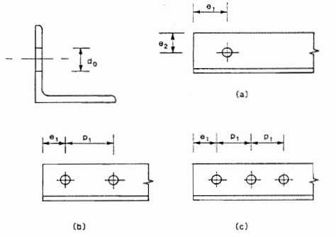
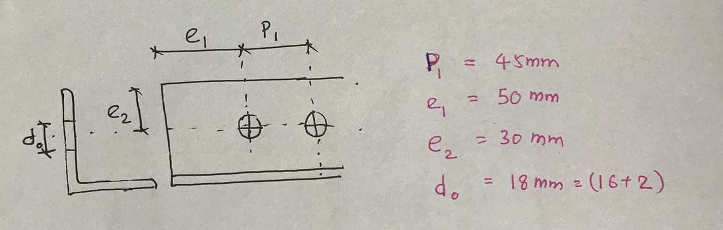
The following figure shows the screw arrangement considered in this calculation example. Values are only considered for this single angle construction.

Particular attention should be paid to design requirements regarding bolt spacing. The minimum and maximum pin spacing, edge spacing, edge spacing, etc. must comply with Section 3.5.
Design parameters
Steel grade S275
The thickness of the angled section is 6 mm.
From EN 1993-1-1 Table 3.1
F j = 275 N/mm 2
F She =430 N/mm 2
The partial safety factors result from Section 6.1.
γ m0 = 1.0
γ m2 = 1.25
Plate cross-sectional area: A = 695 mm 2
Calculate plastic strength from calculation of gross cross section, N Pl, Rd
N pl, Rd = Af j /γ m0 = 695 x 275 / 1.0 = 191.1 kN
The angled section is connected by a leg, and there are two screws in the section. Therefore, assess the capacity of the section in accordance with clause 3.10.3 of EN 1993-1-8.
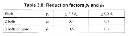
N you, Rd =β 2 A network F Ela /γ M2
β 2 = The reduction factor depends on the slope P1 according to table 3.8 of EN 1993-1-8.

D 0 = 16 + 2 = 18mm
2.5d 0 = 45mm
P 1 = 45 mm – see drawing above
P 1 = 2.5 days 0
From Table 3.8 it follows β 2 = 0.4
As it is a single screw across the entire cross section,
Anet = cross-sectional area – hole area = 695 – 18 x 6 = 587 mm 2
N you, Rd = 0.4 x 587 x 430 / 1.25 = 80.8 kN
Design tensile strength = N t,Rd (design tensile strength) minimum N pl, Rd en u, Rd
N t,Rd = Min (minimum of N pl, Rd in u, Rd ) = Min. ( 191.1 , 80.8 ) = 80.8 kN
Traction force, N Ed.
N Ed. = 75kN
N Ed. /N t, R 75/80.8 ≤ 1
section is enough
The article Construction of steel beams according to BS 5950 can also be used to expand knowledge in the area of steel structures.