This article explains the design of steel columns according to Eurocode 3, EN 1993-1-1, using a practical example. Project explanations are made by referring to the relevant sections of the Code.
For a detailed explanation of the steel support structure, see the article Steel column design according to Eurocode 3 .
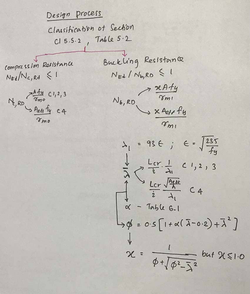
The design process described in the article above is as follows.


Let's start the design process with a practical example.
Design data
- Column dimensions 150x150x 31.1 kg/m
- Steel grade S275
- Column height 3m
- Axial load 500 kN
- For the sake of simplicity, in this example we consider the column with a pin end
Section classification
Let's find out the strength parameters.
t < 40mm
From Table 3.1 of EN 1993-1-1,
fy = 275 N/mm2
ε = √(235/f j ) = √(235/275) = 0.92
From section 6.1:
γ m0 = 1.0
γ m1 = 1.0
H = 39.65cm 2
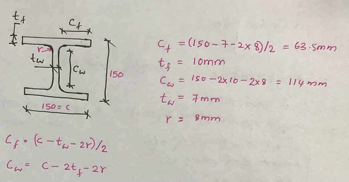

We can calculate thinness limits.
table
C F /T F = 63.5/10 = 6.35 < 9ε = 9 x 0.92 = 8.82; Class 1 section
network
C i /T i = 114/7 = 16.3 < 33ε = 33 x 0.92 = 30.36; Class 1 Section
-
Plastic resistance or transverse resistance, N c, Road
- Non-thin profiles: Class 1
N c,Rd = Af j /γ m0 = 3965 x 275/1 = 1,090.4 kN
After calculating the resistance, the following capacity test must be carried out.
N Ed. = 500 kN
N Ed. /N c,Rd = 500/1090.4 = 0.46 <1
The cross section meets the plastic strength.
- Buckling resistance, N b, Road
First calculate the buckling resistance depending on the section class.
Let's follow the procedure in the design process.
λ1 = 93.9ε = 93.9 x 0.92 = 86.4
When designing the pillar, we need to consider the resistance around each axis (YY and ZZ).
i = radius of gyration
EU JJ = 6.4 cm
EU currently = 3.77cm
M cr = buckling length
Since the two ends of the column are fixed,
M cr = 1.0 x L = 3m
λ¯ = I cr / Iλ 1
YY axis; λ¯ = L cr / Lλ 1 = 3000 / (64 x 86.4) = 0.54
ZZ axis; λ¯ = L cr / Lλ 1 = 3000 / (37.7 x 86.4) = 0.92
Let's determine the α – imperfection factor from Table 6.1 of EN 1993-1-1
Find the buckling curve
h/b = 150/150 = 1 < 1.2
T F = 10 mm < 100 mm
Let's now look at part of table 6.2 of EN 1993-1-1,
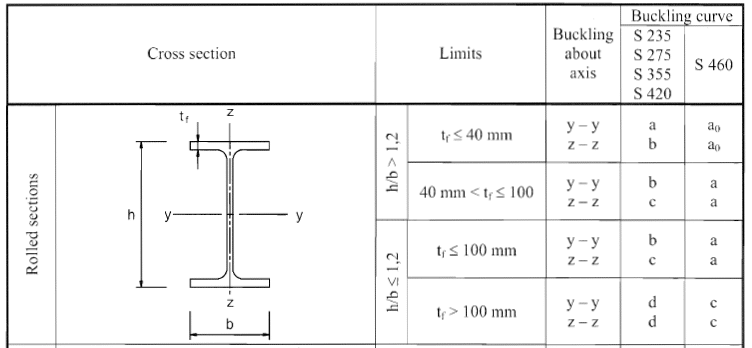

Therefore, the humpback curve results as follows
YY–b axis
ZZ–c axis
From Table 6.1
| Bend Curve | To 0 | A | B | W | D |
| Imperfection factor α | 0.13 | 0.21 | 0.34 | 0.49 | 0.76 |
α on the YY axis = 0.34
α on the ZZ axis = 0.49
Now calculate Ø
Ø = 0.5 ( 1 + α( λ¯ – 0.2) + λ¯ 2 )
About the YY axis
Ø = 0.5 (1 + 0.34(0.54 – 0.2) + 0.54 2 ) = 0.7
About the ZZ axis
Ø = 0.5 (1 + 0.49(0.92 – 0.2) + 0.92 2 ) = 1.1
Calculation of the reduction factor, χ
χ =1 /( Ø + √(Ø 2 –λ¯ 2 )) ≤ 1.0
About the YY axis
χ =1 /( 0.7 + √(0.7 2 – 0.54 2 )) = 0.873 < 1.0
About the ZZ axis
χ =1 /( 1.1 + √(1.1 2 – 0.92 2 )) = 0.587 < 1.0
The lower χ is the critical axis against buckling and lower buckling resistance is available.
Therefore,
χ = 0.587
Now calculate the buckling resistance N b, Road ,
N b, Road = χ A f j /γ M1 – Not thin – Class 1
N b, Road = 0.587 x 3965 x 275/1 = 640 kN
- Capacity check
N Ed. /N b, Road ≤ 1.0
N Ed. /N b, Road = 500/640 = 0.781 <1
The section is ok.
For more information, see the article “Eurocode 3: Design and construction of metallic structures” published on Wikipedia.