You've probably heard of SSD1306 or SSD1315 organic light-emitting diode (OLED) displays. These monochrome screens typically have a similar price range to character screens, providing a more aesthetic appeal. Most significantly, they provide a truly graphical interface to an embedded device.
OLED displays are available on ready-to-use breakout boards that can be easily inserted into virtually any PCB. Instead of simple characters and numbers, OLEDs can display complex graphics where each individual pixel on the screen can be programmed by the user.
SSD1306 or SSD1315 are the names of the OLED driver chips. The official MicroPython repository does not have a driver library for SSD1306. While there are forks of the same library made by other developers that claim to work well with the SSD1315, these claims are currently unconfirmed.
In fact, even the SSD1306 driver available in the official code repository has bugs in the I2C implementation. For our purposes, we will only cover the official SSD1306 driver library with a demonstration of its SPI implementation, which has been proven to work.
SSD1306 is a single-chip CMOS OLED/PLED driver. It can manage a 128×64 dot matrix graphical display. It is designed to control common cathode OLED panels. The chip comes with several built-in features such as 256-step brightness control, display RAM, oscillator, and contrast control. The integrated features of the SSD1306 chip mean there are no additional requirements for a controller or block to interface with the OLED display on a breakout board.
The SSD1306 driver chip is used to control monochrome OLED displays with resolutions of 128×64 (0.96″), 128×32 (0.91″), or smaller OLED displays. The OLED driver uses I2C and SPI interfaces to connect to a microcontroller or microcomputer. Some breakout boards use only the I2C interface, while others offer both interfaces.
The I2C implementation of the MicroPython SSD1306 OLED driver library has runtime errors, so it is worth purchasing an SSD1306 OLED display module with an integrated SPI interface. The SSD1306 OLED display module can display highly complex graphics, including text, bitmap images, and animations.
These OLED displays are popular for designing wearables and IoT devices.
The SSD1306 OLED display
OLED displays for embedded devices come in two standard sizes:
- 0.91″ with 128×32 screen resolution
- 0.96″ with a screen resolution of 128×64.
Monitors are monochrome blue, monochrome white, or blue-yellow. The OLED display module can have a 3/4-pin port, which is for I2C interface only, or a 7-pin interface for 3-wire SPI, 4-wire SPI or I2C interface.
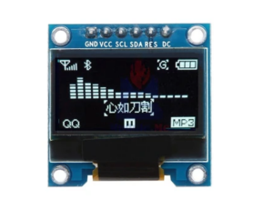
The SSD1306 module that we will test in the tutorial is a 0.96″ screen with a resolution of 128×64. It is monochromatic yellow-blue in color.

The module here has a 7-pin interface, which allows it to interface with any microcontroller or SBC via a 3-wire SPI, 4-wire SPI, and I2C interface.
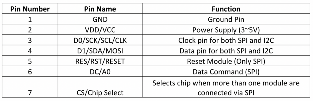
The 7-pin OLED display has this pin configuration:
EU interface of SSD1306 with ESP8266
The SSD1306 OLED module can be connected to the ESP8266 using an I2C or SPI bus. Both SPI hardware and software can be used.
To interface with the I2C bus, connect the SCL and SDA pins on the SSD1306 OLED with GPIO5 and GPIO4 of the ESP8266, respectively. The power supply and ground of the OLED module can be provided through the 3V output and GND of the ESP8266 respectively.
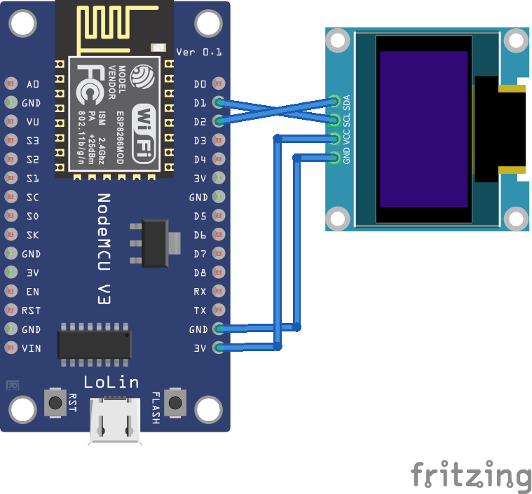
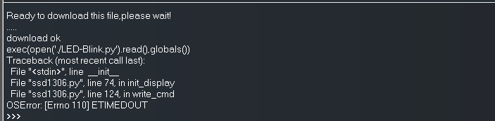
Currently, the I2C implementation of the SSD1306 OLED driver library has runtime errors for ETIMEOUT. Therefore, it is recommended to use SPI to interface with the OLED module.
As mentioned, both hardware and software SPI can be used. SPI software can use any pin capable of outputting SCK, MOSI, RST, DC, and CS. These circuit connections can be used to interface the SSD1306 using SPI hardware and software.

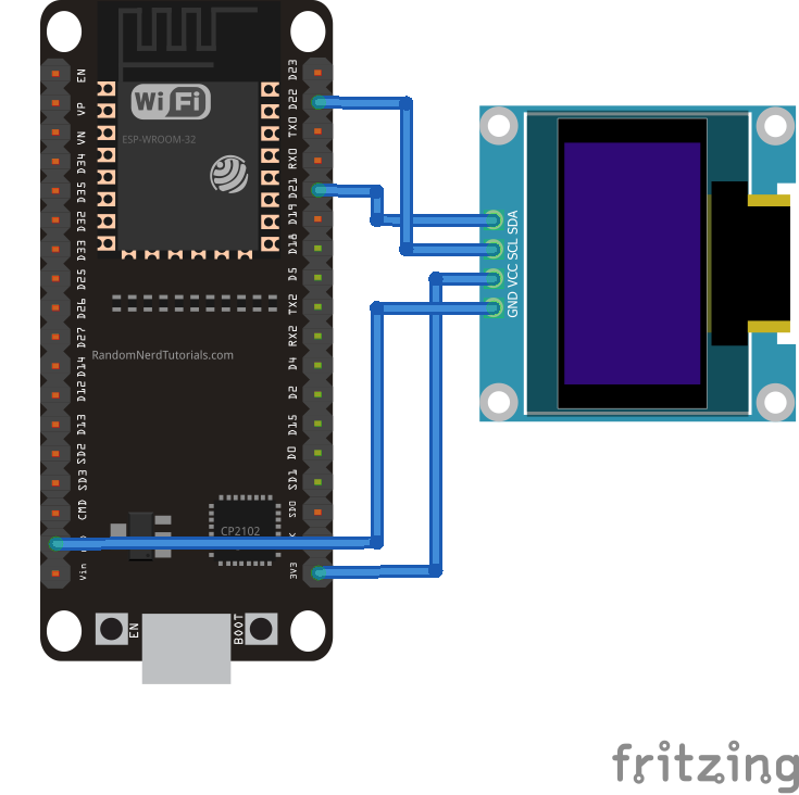
SSD1306 interface with ESP32
The SSD1306 OLED display can be interfaced with the ESP32 using I2C and SPI hardware and software.
To interface via I2C, connect the SCL and SDA pins on the SSD1306 OLED with GPIO22 and GPIO21 of the ESP32, respectively. The power supply and ground of the OLED module can be provided via the ESP32's 3V and GND output respectively.
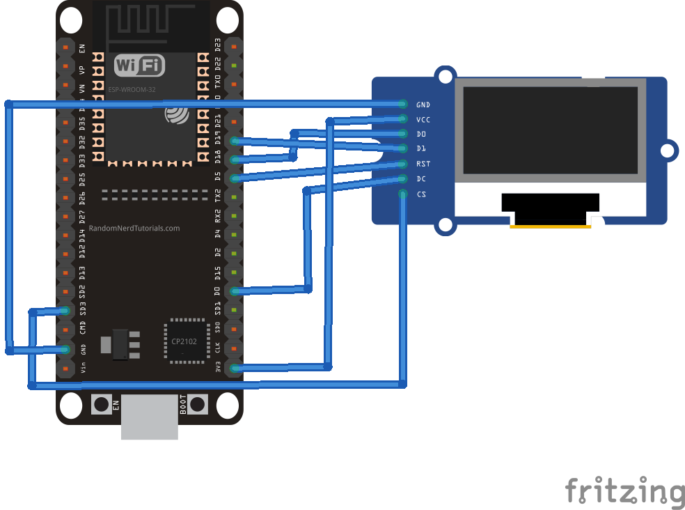
Again, the I2C implementation of the SSD1306 OLED driver library gives the runtime error, ETIMEOUT. Therefore, it is recommended to use SPI to interface with the OLED module. SPI hardware and software can be used. SPI software can use any pin capable of outputting SCK, MOSI, RST, DC, and CS.
The circuit connections can be used to interface the SSD1306 using SPI hardware and software.
MicroPython SSD1306 Driver
The SSD1306 OLED driver library is now part of the standard MicroPython. The library can be found here .
Here is the source code of this library:
The SSD1306 driver code
The SSD1306 OLED driver starts by importing the const class from the MicroPython module and the framebuf module. The const class is used to define the constants of the class members. framebuf is a module designed to manipulate frame buffers such as bitmap images.
This is followed by a declaration of the constants for the SSD1306 registers. The constants receive the hexadecimal addresses of the respective SSD1306 registers.
Next, the SSD1306 class is defined, which takes the frame buffer as the only parameter. The constructor function of the SSD1306 class takes the screen width in pixels, the screen height in pixels, and the external power pin as parameters. These arguments are used to determine the number of pages on the screen, creating a buffer object that can store each page's frame buffer.
The SSD1306 class includes these methods…
- initial_display : initializes the display by setting various parameters such as horizontal resolution, column address, screen clock, contrast, and RAM settings.
- off : turns off the display.
- on : turns on the display.
- Contrast : Sets the screen contrast.
- inverted : inverts the color of the text.
- rotate : rotates the screen.
- show : shows the display screen – as this method is called, the content written to the OLED RAM is displayed on the OLED screen.
The driver uses several methods from the FrameBuffer class of the framebuf module to write text or draw shapes on the OLED screen.
The following methods of the FrameBuffer class are useful in manipulating text and shapes on the SSD1306 OLED.
- FrameBuffer.fill(c) : fills the entire framebuffer with a specified color. The SSD1306 OLED driver uses this method to fill the OLED screen with a monochromatic color.
- FrameBuffer.pixel(x, y(, c)) : Gets or sets the color of a specified pixel. The pixel position is passed as arguments 'x' and 'y.' If used to set the pixel color, 'c' is the color passed as argument.
- FrameBuffer.hline(x, y, w, c) : draws a horizontal line of width 'w', starting at the pixel positions 'x' and 'y'. The horizontal line is filled with the color 'c.'
- FrameBuffer.vline(x, y, h, c) : draws a vertical line with the height, 'h', starting at the pixel positions, 'x' and 'y'. The vertical line is filled with the color 'c.'
- FrameBuffer.line(x1, y1, x2, y2, c) : draws a line between pixels positioned at (x1, y1) and (x2, y2). The line is filled with the color 'c.'
- FrameBuffer.rect(x, y, w, h, c) : draws a rectangle with width 'w' and height 'h', starting at the pixel positions 'x' and 'y'. The edges of the rectangle are filled with the color 'c.'
- FrameBuffer.fill_rect(x, y, w, h, c) : draws a rectangular box with width 'w' and height 'h', starting at the pixel positions, 'x' and 'y'. The rectangular box is filled with the color 'c.'
The monochrome OLED display can only have two colors for each pixel. It is filled with the monochromatic color of the OLED or the inverted color. Therefore, the value of argument c can only be '0' or '1'.
The '0' indicates the true monochromatic color and the '1' indicates the inverted color. The pixel position can be specified as 0~128 along the x-axis and 0~64 along the y-axis in the case of an OLED resolution of 128×64.
- FrameBuffer.text(s, x, y(, c)) : writes a text string to the OLED display. Text starts printing on the screen from the pixel positions, 'x' and 'y'. Text color can be set to 'c'.
The class definition of the SSD1306 is followed by the class definition of another class, the SSD1306_I2C . This class has a constructor function and two methods – write_cmd to write the OLED command and write_data to write the display data.
Currently, running this class is generating a runtime error.
The SSD1306_SPI class is defined by the SPI bus implementation for the SSD1306 OLED. This class has a constructor function and two methods – write_cmd to write the OLED command and write_data to write the display data.
Loading the OLED driver with uPyCraft IDE
To upload the OLED driver for ESP8266 or ESP32 using uPyCraft IDE, connect the board to a computer using a USB cable. Ensure the MicroPython Firmware for ESP8266/ESP32 is loaded.
Select the ESP8266/ESP32 COM port to ensure it is connected by navigating to Tools->Serial and choose your MicroPython board by navigating to Tools->Board. Then connect the board to the uPyCraft IDE by clicking the connect button.
![]()
Once the board is connected, you can browse boot.py in the device folder. To add the SSD1306 OLED driver, create a new file by navigating to File->New or clicking the New button.
![]()
Copy the SSD1306 OLED driver library code and save the file as ssd1306.py. Finally, click the Download and Run button to load the library file into the ESP8266/ESP32.
![]()
Once the file is loaded, it can be imported into the main script and used to interface the OLED display.
Loading the OLED driver with Thonny IDE
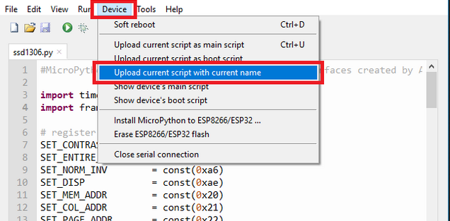
If you are using Thonny IDE, create a new file by navigating to File->New. Copy the SSD1306 OLED driver library code here and save the file as ssd1306.py. To upload the file to ESP8266/ESP32, navigate to Device -> Upload current script with current name.
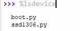
To verify that the file was successfully loaded into the ESP8266/ESP32, type this command in the shell:
%lsdevice
It will return a list of files uploaded to the board. The list must include ssd1306.py.
Displaying sensor data on SSD1306
The SSD1306 OLED display can be used with ESP8266/ESP32 to display sensor data, show network parameters, or display insights received from a remote IoT server.
The text method of the FrameBuffer class requires a string argument. Values returned by sensors, network parameter values, or IoT insights are often integer or floating point values. These values must first be converted to a string using the cPython/MicroPython str function.
This is a valid example of converting an integer or floating point value from a sensor to a string.
temperature = 25
string_temp = str(temp)
The string object can be passed directly as an argument to the text method to display on the OLED.
oled.text(temp_string, 0, 0)
oled.show
Displaying text on SSD1306 with ESP8266
Now let's display text messages on the SSD1306 OLED. In this tutorial, SSD1306 is interfaced with ESP8266.
Required components
1. ESP8266x1
2. SSD1306 OLED with SPI x1 interface
3. Connecting wires/jumper wires
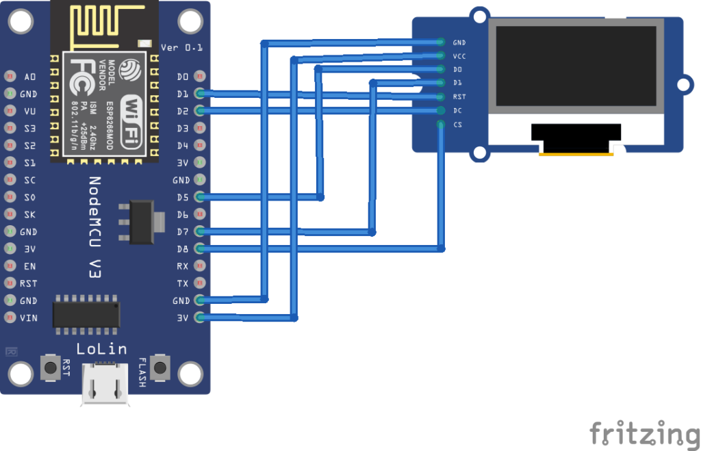
Circuit Connections
We connect the SSD1306 OLED to the ESP8266 using SPI software. The DC, RST and CS pins of the OLED are connected to GPIO4, GPIO5 and GPIO15 respectively. The D0 and D1 pins of the OLED module are connected to GPIO14 and GPIO13. The VCC and GND pins of the OLED module are connected to the 3V and GND output of the ESP8266.
The MicroPython script
How it works
The OLED display module interfaces with ESP8266 using SPI software. The ssd1306 class methods are used to control the OLED, while the framebuf module methods are used to print text messages on the OLED.
The code
Save the above code as main.py and upload the file to ESP8266 by clicking the Download and Run button. The code starts by importing the Pin and SoftSPI classes from the machine module. The ssd1306 module is imported, which must first be loaded into the ESP8266. The sleep class from the time module is also imported.
An object, espi is created from the SoftSPI class, which is instantiated with baud rate 500,000 Hz, polarity 1, phase 0, as well as SCK pin to GPIO14 pin and MOSI pin to GPIO13.
The MISO pin is not used with the OLED module. GPIO12 receives the MISO for SPI software. The DC, RST, and CS pins are configured for GPIO4, GPIO5, and GPIO15, respectively. These pin constants are used to create an object of class SSD1306_SPI oled. The class object is instantiated for a screen width of 128 pixels and a height of 64 pixels. The text is printed on the SSD1306 display by calling the oled.text method. It is shown on the screen when the oled.show method is called.
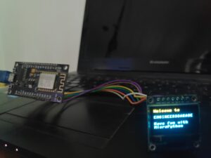
In the MicroPython script above, two text messages are displayed on the OLED screen at two-second intervals. The sleep method is used to provide the delay between the two messages.
The results
Video: