Note: It is recommended to follow this series of VHDL tutorials in order, starting with the first tutorial .
In the previous tutorial, VHDL Tutorial – 17 we designed a JK flip-flop circuit using VHDL.
For this project, we will:
- Write a VHDL program to build the T flip-flop circuit
- Check the program output waveform (the digital circuit) with the flip-flop truth table
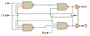
The T flip-flop with an active high enable and reset input circuit:
Truth table
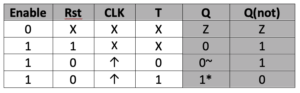
- Note 1: when T = 1, the Q output always alternates (from 0 to 1 and 1 to 0)
- Note 2: when T=0, output Q maintains its previous state
Now let's write, compile and simulate a VHDL program. Then we will get the waveform output and check it with the given truth table.
Before you begin, be sure to review the step-by-step procedure provided in VHDL Tutorial – 3 for designing the project. This will ensure that you correctly edit and compile the program and waveform file, including the final output.
Here. We used a behavioral modeling style to write the VHDL program and build this flip-flop circuit because it is the preferred model for sequential digital circuits.
VHDL Program
ieee library;
use ieee.std_logic_1164.all;
entity T_flip_flop is
port (clk,t,en,rst: in std_logic;
Q: out std_logic;
Qnot: out std_logic);
end T_flip_flop;
TFF_arch architecture of T_flip_flop is
signal operation: std_logic;
to start
process(clk, rst) is
to start
if(en='0′) then op<='Z';
elsif (en='1′ and rst='1′) then
op <= '0';
elsif (clk'event and clk='1′ and en='1′) then
if(t='1′) then op <= not op;
else op <= op;
end if;
end if;
end of the process;
Q <= op;
Qnot <= non-operational;
end TFF_arch;
To refresh your memory on how this works, read the first two VHDL tutorials ( 1 and 2 ) in this series.
Then compile the above program, creating and saving a waveform file with all the necessary inputs and outputs listed (and be sure to apply all the different input combinations). Then simulate the project. You should get the following result…
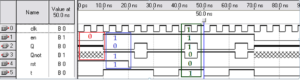
As shown in this figure, three cases are highlighted in red, blue, and green.
- Case 1: when en=0 -> both outputs are at high impedance
- Case 2: when en=1 and rst=1 -> Q=0 and Qnot = 1 (the flip-flop is reset)
- Case 3: when en=1, rst=0 and clk=1 and T=1 – > Q = 1 and Qnot = 0 (the output alternates between 0-1)
Be sure to check the different input-output combinations against the circuit truth table.
In the next tutorial, we will learn how to build a 4-bit binary counter using VHDL.