Any AVR microcontroller based board that follows the standard Arduino schematic and is flashed with the Arduino bootloader can be called an Arduino board . Arduino is known as open source hardware since the standard schematic is open to everyone and anyone can make their own version of the Arduino board following the standard schematic. All Arduino boards must be compatible with the Arduino IDE, which can be used to program Arduino boards. The Arduino IDE is also open source and anyone can contribute their libraries to the Arduino. There is no other tool available that helps in easy prototyping like Arduino. The Arduino board has all the necessary circuitry to make the integrated AVR microcontroller work. The output or inputs can be taken from the boards or supplied to the board using convenient connectors. Digital and analog inputs and outputs are available on all Arduino boards. Arduino boards can also communicate with other devices using standard communication ports like USART, IIC and USB, etc. The most impressive thing is that most Arduino boards are breadboard compatible, which makes both hobbyists and developers happy.
When it comes to programming the Arduino board, anyone who has basic knowledge of C programming can quickly start using the Arduino IDE. It is very simple to understand and has built-in functions for almost any simple or complex task. There are many libraries available that can be used to interface the Arduino board with any other devices . It is difficult to find a hardware module whose interface code is not present in the Arduino. Furthermore, there are many examples that can help someone get used to Arduino in a very short time.
This article discusses the steps needed to get started with Arduino and explains how to code a simple blinking LED code .
The first thing to do is select the Arduino board that meets the requirements. Visit the Arduino website where you can get all the details about Arduino boards and software. It is recommended that beginners use Arduino Duemilanove board or Arduino One board. Those who are used to dealing with hardware, soldering, etc. can choose the Arduino Pro-Mini board. Full details of the available Arduino boards can be found on the Arduino website itself . This article and the following ones are explained based on the Arduino Pro-Mini board and IDE version 1.0.3 for Windows. The advantage of this board is that it comes in a very small size; Breadboard compatible Burg Stick connectors can be soldered as per our requirements. It is very breadboard compatible and takes up much less space than a typical breadboard.

Fig. 2: Typical Arduino Pro-Mini board
The only difficulty is that another board is needed to load the program via the USB port. The compatible USB to TTL Converter board can be obtained from your nearest retailers or by purchasing online. The two boards are so economical that together they cost less than other basic Arduino boards.
3: External USB to TTL Converter Board for Arduino Programming and Serial Communication
The latest version of the Arduino IDE can be downloaded from the Arduino website, available for Windows, Linux, Mac, etc. Just copy the entire folder to a preferred location on your PC, open the folder, click on the Arduino icon and that's it, there's no need to install.
Figure 4: Download the Arduino IDE from the Arduino website
The programming language is based on C and anyone who has a basic idea can quickly start using it. Furthermore, there is a separate page discussing about the programming details just where one can refer all the details of the Arduino programming language.
If everything was done correctly, the Arduino IDE opens and looks like the following image in Windows;
Fig. 5: Arduino IDE software window
The first step is to save the project in a folder selected to contain all Arduino projects and experiments. Click on file -> save as, select the desired folder and give the file name. For all experiments with Arduino it is recommended to create a folder called “ARDUINO WORKSPACE” and save this specific project as “_1_led_blinking”. Sketch names can only consist of ASCII characters and numbers (but cannot start with a number). They must also be less than 64 characters. The Arduino sketch is saved in '.pde' file format.
Figure 6: Saving the file name on Arduino
Now go to the examples and find the basic LED blinking code as shown in the following image;
Fig. 7: LED code flashing in the File Menu
Now a separate window opens with the code that should not be edited by the user, as it is functional code and should be kept as such for future references. Select all and copy and paste all the code into the _1_led_blinking window and close the new window with 'blinking code' safely.
All Arduino codes have a small description about it and the hardware connections at the beginning of the code file itself, as marked inside the green box in the following image.
Fig. 9: Code description and hardware connections
There is a built-in LED connected to digital pin number 13 on the Arduino pro-mini board and this specific code is used to blink this LED with a delay.
An Arduino code has two basic functions, namely “setup” and “loop”. The setup is the function where all initial configurations such as defining the pin as input/output, initializing serial communication with baud rate, etc. The loop is actually an infinite loop within which the rest of the code must be written. User-defined functions, if any, must be written separately outside of setup and loop and can be called from inside both.
The pinMode function is a built-in function used to define a specific pin as input or output. The first parameter is the pin number and the second parameter suggests whether the pin should be input or output.
For example, to make pin number 5 as output
pinMode (5, OUTPUT);
To make pin number 6 as input
pinMode(6, INPUT);
In this specific example, pin13 is already defined as LED using the instruction
internal led = 13
and then came the following statement
pinMode(led, OUTPUT);
which can make the 13th pin of the Arduino board as output.
digitalWrite is another function that can be used to write a digital value (logic 0 or logic high) to a certain pin that has already been output using the pinMode function.
For example, to make pin number 5 as logic high
digitalWrite(5, HIGH);
And to leave the same logic pin low
digitalWrite(5, DOWN);
The delay function is a very useful function for almost all projects and can generate a delay in milliseconds between code steps.
For example, to generate a 5 second delay,
delay(5000);
Once the coding is done, it's time to check the code and Arduino is so easy to use that people won't get many errors. There is a code check button in the top left corner of the IDE as shown below;
10: Code check button -Arduino top left IDE window-
Once the verification is done, the code is ready to be uploaded to the board. Connect the card to the PC's USB port and install the driver that came with the card. After installing the driver, go back to the Arduino IDE and select the board from the list using tools>boards>arduino pro mini
Fig. 11: Selecting Arduino Pro Mini in the IDE window
After selecting the card, you must also select the COM port to which the card is connected, as shown in the following image;
Fig. 12: Tools COM4 port
Now try to upload the code to the board by clicking the upload button as shown in the image below;
Fig. 13: Loading Code
Now you can try changing the delay or connecting an external LED to another pin and all that basic stuff. No separate power supply is required as the Arduino Pro-Mini board is USB powered.
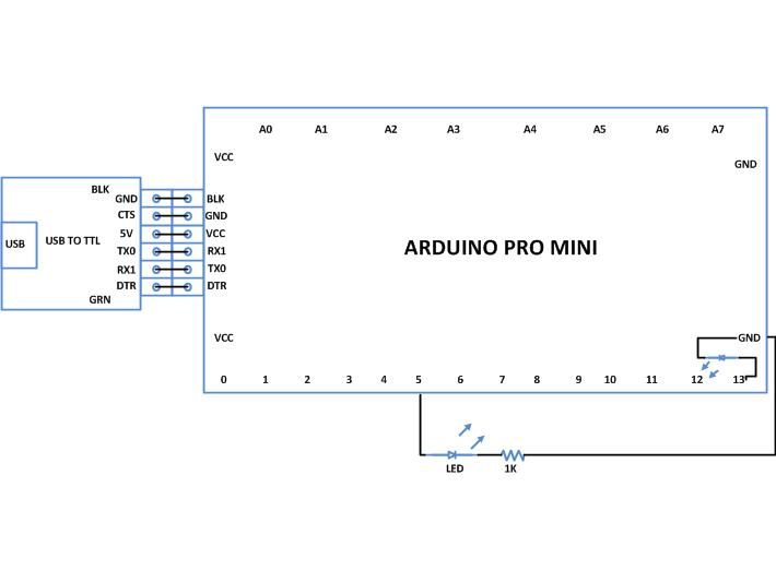
Refer to the code and circuit to blink an external LED connected to pin number 5 of the Arduino board.
Project source code
 ###


 // Pin 5 has an LED connected on it through 1K resistor.

 // give it a name:

 int led = 5;

 // the setup routine runs once when you press reset:

 void setup {

 // initialize the digital pin as an output.

 pinMode(led, OUTPUT);

 }

 // the loop routine runs over and over again forever:

 void loop {

 digitalWrite(led, HIGH); // turn the LED on (HIGH is the voltage level)

 delay(1000); // wait for a second

 digitalWrite(led, LOW); // turn the LED off by making the voltage LOW

 delay(1000); // wait for a second

 }

###
Circuit diagrams
| Circuit Diagram-Introduction-Arduino |
 |
Project Components
- Arduino ProMini
- LED
- Resistor
Project video