Demonstration of Raspberry Pi-based digital door peephole
A peephole, peephole, or peephole is a small opening in a door that allows viewing from the inside to the outside. These door holes allow you to see the outside of the door without opening it. Typically, these door holes have fisheye lenses to give a wider view of the outside. In this project, we developed a digital version of the peephole with the help of a Raspberry Pi camera and a Raspberry Pi board. The first apparent advantage of a digital peephole is that it can be easily hidden in a door design compared to conventional peepholes. Secondly, a camera-based peephole offers a 180˚ external view. A programmatically sophisticated version of the same peephole can provide features such as visitor identification (through face detection), registration of unidentified visitors, and playback of pre-recorded voice messages for specific visitors.
The device developed in this project uses a Raspberry Pi camera, Raspberry Pi board, a PIR sensor and a small LCD screen with HDMI input. It can be easily integrated into any door and easily hidden in a door design. The prototype demonstrated here is developed on Raspberry Pi 3. The commercial or hobbyist version of this project can be developed using Raspberry Pi Zero to make the design compact. Once installed in a port design, the entire device can be powered with the help of a 5V 2A adapter.
Required components
- Raspberry Pi 2/3/4 or Raspberry Pi Zero x1
- Raspberry Pi x1 Camera
- Ribbon cable for connecting Raspberry Pi x1 camera
- PIR sensor x1
- 5″ HDMI LCD
- Connecting wires/jumper wires for testing prototype on a breadboard
Circuit Connections
When testing the project, you can interface the Raspberry Pi with a desktop monitor. Connect a small HDMI LCD to the Raspberry Pi's HDMI port. Connect the Raspberry Pi camera to the CSI port on the board.

Demonstration of connecting the Raspberry Pi-based camera to the CSI port peephole
To interface the PIR sensor with Raspberry Pi, connect the PIR sensor input pin to any GPIO. Here pin 7 of the board is connected to the PIR sensor input pin. Connect the VCC and GND pins of the PIR sensor to the 3.3V output and ground pins of the Raspberry Pi.

PIR sensor
It should be noted that the sensitivity of the PIR sensor needs to be adjusted to obtain proper digital input. The PIR sensor is calibrated to provide defined output during program testing.
Python Code

How the project works
The Raspberry Pi camera and PIR sensor are installed in front of the door. The Raspberry Pi itself is installed on the back of the port. The port has a small horizontal cutout to pass through the Raspberry Pi camera ribbon cable. The entire circuit is powered from the back of the port with the help of a power bank or DC adapter. A 5-inch LCD is connected to the Raspberry Pi on the back of the port.
The user can run the python script while the device turns on and the Raspberry Pi boots up. The python script can be started automatically at startup. As the python script runs, it launches an external view on the LCD. To test the display, the Raspberry Pi can also be connected to a desktop monitor with an HDMI input. The preview continues without interruption while the script is running. After starting a preview, the Raspberry Pi continuously checks the digital signal from the PIR sensor. Here the PIR sensor is calibrated to provide a HIGH digital output as it detects any movement outside the door. Upon detecting any movement, the Raspberry Pi camera captures the external image and stores it with a file name with increasing number.
The code
The python script starts with importing the PiCamera class from the PiCamera library and the RPi.GPIO class from the GPIO library. If the PiCamera library is not installed, it must be installed using pip or installed manually. Similarly, the time class is imported from the sleep library. The GPIO is configured for board numbering and board pin 7 is assigned to the PIR sensor input. Variables to contain the image number, image name and image URL are declared. GPIO.setwarning is set to false.
An object of the camera class is instantiated using the Picamera method. The PIR sensor pin is defined as a digital input. The camera preview is started using the start_preview method. A 5 second delay is provided after the preview starts. This helps stabilize the camera for ambient light and exposure.
An infinite loop is run to capture images of any movement outside the door. If the PIR sensor detects any movement, it will provide a logic HI output. If the PIR sensor output is HIGH, the image number is increased by 1 and is concatenated to the string “image” in the variable 'imagename'. The image name is appended to a file path in the 'pathname' variable. The external image is captured with the updated file location using the capture method. The new image name is recorded in the console using the print function. A 5 second delay is provided after capturing an image.
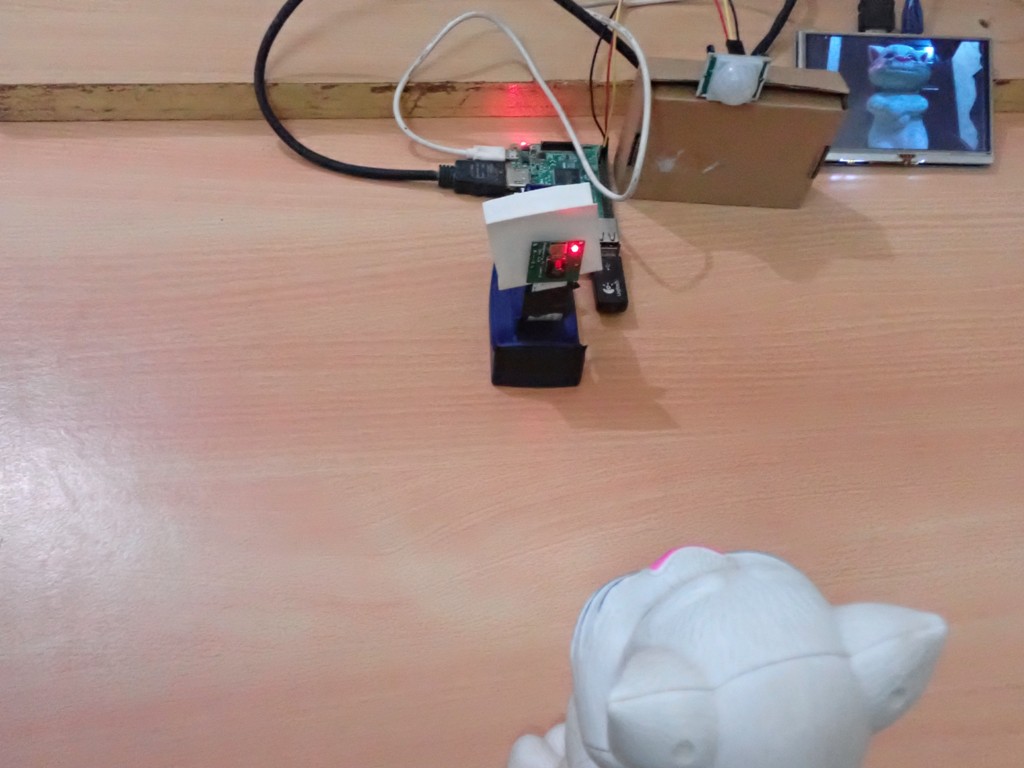
Demonstration
The following images and videos are from testing the device using a desktop monitor. Observe how the device captures the image of the outside by detecting each movement.

Demonstration of Raspberry Pi-based digital door peephole

Demo video