The performance of each electronic system or electronic circuit depends on the power source that energizes the circuit or system. It supplies the required current to the circuit. Any disturbing noise in this power supply may cause problems in the functioning or operation of the circuit. If there is any deviation in this power level, the circuit may not work correctly. The accuracy and precision of the circuit operation depend on it. In some circuits all calibration is done at this voltage level. Therefore, all these calibrations become false if there is a fluctuation in the supply level.
There are two types of power supplies
1) Unregulated power supply
2) Regulated power supply
Unregulated power is used in some circuits where there is not much change in the required load current. The charging current remains fixed or the deviation is much smaller. Because in such an offer
1) Output voltage decreases as load current increases
2) The output voltage ripple increases as the load current increases
Therefore, this type of power supply cannot be used where there is a noticeable change in load current frequently. But although many circuits work on unregulated power supply because they require few components and the design is also very simple. Also, some fluctuation in supply level can be tolerated due to change in load current. Regulated power supply is required in digital circuits, circuits in which components cannot tolerate even 1% change in power level such as microcontroller, microprocessor, etc.
So here I am giving the steps to design a regulated power supply, including which components should be chosen to have the required regulated output voltage with the required current. The procedure requires calculations based on some design equations, some assumptions and approximations that we must adopt during the project.
Consider the following notification
E rms : rms value of AC voltage (transformer secondary voltage)
And I : maximum value of AC voltage
V DCNL : no-load DC voltage
V dcFL : full load DC voltage
R ó : Internal resistance
EU : full load output current
V Lmin : minimum unregulated power output voltage
V rms : rms value of the ripple
?V o : choose the ripple voltage
Following equations – relationships are used in power supply design
V DCNL =E I = E rms / 1.41
V dcFL = V DCNL –R o L I
?V o = EU I / (200ºC)
?V o = 3.5 V rms
V Lmin =V dcFL – ?V o / 2
So let's start designing
AIM: 5V @ 1A regulated power supply design
Procedure:
We have to design 2 separate sections
1) Regulated section
2) Unregulated section
Regulated section design –
Step 1: Select the voltage regulator chip
Since we are designing a regulated power supply, we need a voltage regulator chip. There are so many voltage regulator chips available. They are broadly classified into different categories based on
1) Polarity: positive, negative or double
2) Fixed output or variable output
3) Required output current 0.1 A – 5 A
Here we require fixed and positive power supply with current capacity of 1 A. So we have to choose LM7805 voltage regulator chip.
Step 2: Input – Output Capacitive Filter
The input capacitor is necessary to suppress or minimize any ripple or variation in the input applied to the regulator chip. Its typical value is 0.33µF as specified in the datasheet. This can be overlooked if the regulator chip is connected too close to the rectifier filtering capacitor. It is only necessary when the distance between the rectifier output and the regulator input.
The output capacitor is necessary to suppress any spike or glitch in the fixed output voltage that may occur due to the transient change in the AC input. Its typical value is 0.1 µF as specified in the datasheet.
This completes the design of the regulated section.
Unregulated section project –
Powers the regulated section. Your rectifier + filter. The most necessary thing is that the input given by this section to the regulated section is at least 3 V greater than the required output voltage. This is known as ' headroom ' for regulator chip. This gives us
V Lmin =V operation + free height
= 5 + 3
= 8V
For this section, we have to select the transformer, diode and capacitor.
Step 3: Selecting the Capacitor
Let's assume the capacitor is a 1000 µF electrolytic capacitor. We need to find out its working DC voltage WLDC but it depends on V DCNL as
WLDC = VDCNL + 20% VDCNL
So after finding V DCNL we can calculate it.
From this capacitor value we can find ?V as
?V o = EU I / (200ºC)
So for I I = 1 A and C = 1000 µF
?V o = 1/200×1000×10 -6
= 5V
From ?V o e V Lmin , V dcFL can be calculated as
VdcFL = V Lmin + ?V o / 2
= 8 + 5/2
= 10.5V
V dcFL is related to V DCNL as
V dcNL = V dcFL +R o L I
Is the value between 6? to 10?. Assuming R is like 8?
VDCNL = 10.5 + 8×1
= 18.5V
Now calculate the required WLDC
WLDC = VDCNL + 20% VDCNL
= 18.5 + 3.7
= 22.2V
We always have to look for a higher value than this. So choose a capacitor with WLDC of 25 V. So finally our capacitor is
C = 1000 µF at 25 V
Step 4: Diode Selection
Selecting a diode means finding the current capacity and PIV of the diode.
1. Current capacity I C > I I this means Ic can be 1 A or more
2. PIV = VDCNL + 20% V DCNL = 22.2. again opting for a higher value which is 25 V
Finally, the necessary diodes are with
D = 1A at 25V
All diodes of the 1N4004, 1N4007, 1N4009 series meet these criteria.
Step 5: Selecting a Transformer
The rms value of the transformer output is given by
And rms = And me / 1.41
But E m = V dcNL., So
E rms =V DCNL / 1.41
= 18.5 / 1.41
= 13.12 VAC
So we can select anyone
- 1) 9 – 0 – 9 or 7.5 – 0 – 7.5 secondary voltage center tap transformer
- 2) Transformer without center tap of 0 – 15 or 0 – 18 secondary voltage
The nominal current for the transformer secondary must be at least 1.8 I. This means the current rating could be 2A.
Finally select a transformer with
T = 230/15 VAC @ 2A
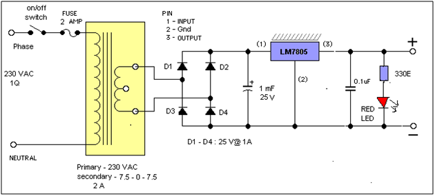
The final design schematic is shown in the circuit diagram tab.
Circuit diagrams
| fixed power supply |  |