
Introduction
In 2013, the company's structural components workshop presented two Trumpf CO2 laser cutting machines, model CP3000.
Due to the lack of experience in maintenance and repair of this type of equipment, most breakdowns depended on the manufacturer's after-sales service, resulting in long repair cycles and high maintenance costs.
By analyzing the causes of failures, corrective and preventive measures were formulated and an A4 Equipment Failure Report was created to prevent future failures.
During this process, maintenance experience was continuously accumulated and the skills of equipment maintenance personnel were improved, gradually achieving a transition from outsourced maintenance to a self-sufficient + outsourced maintenance model.
1 “High voltage drop” fault repair
1.1 Fault description:
During the cutting process, the laser monitor suddenly displayed an alarm “2104”, which showed that there was a “high voltage drop”.
After restarting the equipment, it operated normally, but thereafter intermittent alarms occurred during the cutting process and the frequency of alarms increased.
1.2 Analysis of Causes:
According to the working principle of the laser, there are five possible causes for this alarm.
(1) Impurities in high purity gases, especially excess water. Moisture entering the resonant cavity will cause the resistivity of the plasma in the cavity to decrease, resulting in an abnormal increase in the high voltage power supply current.
(2) Leak in the resonant cavity, with ambient air entering the cavity. When the resonant cavity is working normally, it is a negative pressure environment. If there is a leak point, ambient air will enter the cavity.
(3) Leakage of the heat exchanger or its sealing ring, allowing cooling water to enter the resonant cavity.
(4) Incorrect gas mixture ratio. An incorrect mixing ratio may result in a decrease in laser power, and the laser will increase power by appropriately increasing the high voltage current of the power supply. When the high voltage current exceeds a certain range, an alarm will occur.
(5) Vacuum pump return. If the vacuum pump's one-way valve is not tightly sealed, residual gas with oil vapor will flow back into the resonant cavity, contaminating optical components such as dirty lenses and causing a decrease in power.
1.3 Troubleshooting:
(1) The gas was switched to another laser and used normally, ruling out impurities in the gas as the cause.
(2) The resonant cavity was evacuated below 1 kPa (10 mbar), all solenoid valves were closed, and after 20 minutes the pressure increased by 40 Pa (0.4 mbar), meeting the equipment manufacturer's requirements, ruling out leaks and heat exchanger leakage as the cause.
(3) The gas mixing ratio was checked and readjusted. After adjustment, the fault still existed and the frequency did not decrease, ruling out an incorrect gas mixture ratio as the cause.
(4) The piping between the vacuum pump and the resonant cavity has been removed and cleaned of oil stains. Before dismantling the front mirror, rear mirror and folding mirror, they were cleaned, reinstalled and adjusted. However, the fault still existed, eliminating vacuum pump backflow as the cause.
1.4 Additional troubleshooting:
Analysis and troubleshooting of the equipment's operating status were carried out. During the actual cutting process, it was observed that before the “high voltage drop” alarm occurred, the power suddenly rose to about 1200W, then the alarm occurred.
The “heating” mode was activated and the heating power was gradually increased. When the power setting reached 1500 W, the measured output power was only 1200 W, and there was a “filamentation” phenomenon in the 1# resonant cavity.
After running for about 20 seconds, the laser gave a “high voltage drop” alarm and the power supply gave an “overcurrent” alarm. The laser power supply electronics have been checked and found to be normal.
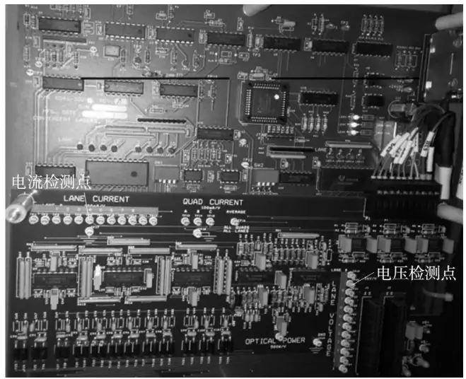
The detection voltage output of resonant cavity 1# was measured on the power monitoring circuit board (Figure 1), which was 8.4V, while the voltage of resonant cavity 2# was about 7.6V, indicating that the oil-immersed booster power supply of the 1# resonant cavity has been damaged.
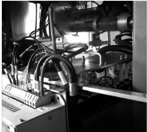
The oil-immersed power supply unit was disassembled (Figure 2), and the electronic components such as the transformer, boost capacitor, and boost diode of the 1# resonant cavity boost power supply were measured, and all were considered normal.
The voltage reduction detection circuit was measured and one of the redundant 100k resistors was found to have a measured value of 116kΩ. It was preliminarily judged that the reason for the “high voltage drop” alarm was due to damage to this resistor.
1.5 Emergency measures:
A 100kΩ, 2W resistor was removed from another old circuit board and used to replace the damaged resistor. The “heating” mode was activated and the power setting was gradually increased until reaching the maximum power of 3000W.
The operating status of the laser was observed, no “high voltage drop” alarm occurred, and there was also no “filamentation” phenomenon.
1.6 Analysis of the true causes:
(1) The 16 voltage reducing resistors in two laser machines were tested and their resistance values were 5% higher than normal. These resistors are carbon film resistors, which have low power and are easily oxidized by voltage shocks, gradually increasing their resistance value.
Therefore, it was considered that the use of carbon film resistors in circuit board design was unreasonable, and more impact-resistant and stable metal film resistors should be used.
(2) Other issues discovered during the troubleshooting process included a large deviation between the gas mixture ratio and the factory setting, as well as inadequate substitution and use of high purity gas.
1.7 Corrective and preventive measures:
(1) Purchase 100kΩ and 2W metal film resistors to replace defective ones and avoid such failures.
(2) Modify the operation and maintenance manual, add periodic voltage and current checks for the power supply, adjust the gas mixing ratio, and add regular inspection and adjustment items. Standard ventilation operating procedures and usage requirements must be developed and disseminated through training.
(3) Third-party inspections of high-purity gases (N2, CO2, He2) used in the laser machine, and the supplier must rectify any non-compliance issues within a specified time frame.
Solving the problem of frequent collision between the cutting head and sheet metal
2.1 Problem description:
(1) Due to the frequent warping of sheet metal, the cutting head of the laser cutting machine collides with the warped sheet metal, causing damage to components such as capacitive head, ceramic body, cutting nozzle and four-link component.
After the collision, replacing spare parts and adjusting equipment leads to considerable loss of time that delays production.
(2) In 2018, a total loss of 103,000 RMB occurred due to component collision damage, detailed in Table 1 (downtime losses not included).
Table 1: Statistics of losses caused by two laser collisions in 2018.
| Damaged component | Amount /parts |
Unit price /10,000 yuan |
Total amount /10,000 yuan |
Comments |
| Capacitor head | 6 | 0.3 | 1.8 | To be used after third-party repair |
| Capacitor head | two | two | 4 | Can't repair, need to buy |
| Insulation gasket | 1 | 0 | 0 | New spare part |
| Ceramic body | 20 | 0.02 | 0.4 | Self made |
2.2 Root Cause Analysis
Analyze the possible causes of the five elements: people, machine, material, method and environment.
(1) People: The new employee is not proficient in the operation and cannot handle or deal with the sheet metal warping in time. The operator has little sense of responsibility and does not deal with situations where collisions may occur. After the collision, the coaxial was not readjusted, resulting in the deflection of the laser beam and the burnout of the capacitor head; the tracking was not adjusted in time, resulting in another collision.
(2) Machine: The cutting head's movement response to collision is not sensitive enough and cannot be stopped in time when a collision occurs, which leads to the expansion of accidents.
(3) Materials: The internal stress of the plate is large and the plate deforms due to the release of stress caused by heating during cutting.
(4) Method: Not enough attention is paid to adjusting the cutting path, and parts that are prone to warping are not considered to avoid them as much as possible; micro connections are not used.
(5) Environment: The short plate storage racks, long storage time and personnel trampling cause the plates to bend, making them easy to deform during cutting.
2.3 Investigative and Rectification Measures
(1) Train and evaluate all operators and establish a corresponding reward and punishment system.
(2) Adjust the sensitivity of the collision motion response to the highest level without affecting the use.
(3) Smooth the plate before placing the machine to release some of the internal tension.
(4) Optimize the cutting path during programming and layout, avoiding parts that may warp; use microconnections to reduce the likelihood of part deformation.
(5) Extend the dish storage rack to avoid sinking and bending at both ends; redesign plate storage area, install barriers to prevent personnel from walking and stepping.
After implementing the above measures, the frequency of collision problems has decreased slightly, but the problem has not been completely resolved.
2.4 Video and Photo Analysis for Investigation
(1) The root cause of the problem that has not been resolved for a long time is that professional personnel are not on site when collisions occur, and it is impossible to restore the situation at that time.
Later, by installing monitoring on the equipment and taking photos after each collision, analyzing video and photo data, it was found that collisions occurred during the empty route from the end of a cut to the starting point of the next cut.
Before empty operation, the cutting head will rise a certain distance (lifting height).
By trying to increase the lifting height, the problem can be solved.
(2) Study the control program. Observing the cutting program, it was found that the lifting of the cutting head during no-load operation is controlled by subroutines 1012 and 1022. Open the subroutine to analyze the control principle.
(3) Cutting head height control principle. Use a sensor to detect and calculate the distance to the plate height. When no-load operation is required, the Z axis moves in the negative direction until it stops when the sensing height is 10 mm, and then performs no-load operation action.
2.5 Root Cause Analysis
(1) There are the following shortcomings in this control method: the sensor can only accurately detect the distance of 10mm. The greater the distance, the greater the error. It cannot avoid collisions and can only stop running after a collision occurs.
Using PID control, there is a problem of response delay when a collision occurs, which leads to the expansion of collision accidents. It can only sense the situation where the plate's height drop changes uniformly, and cannot sense the situation where the plate's height drop changes suddenly.
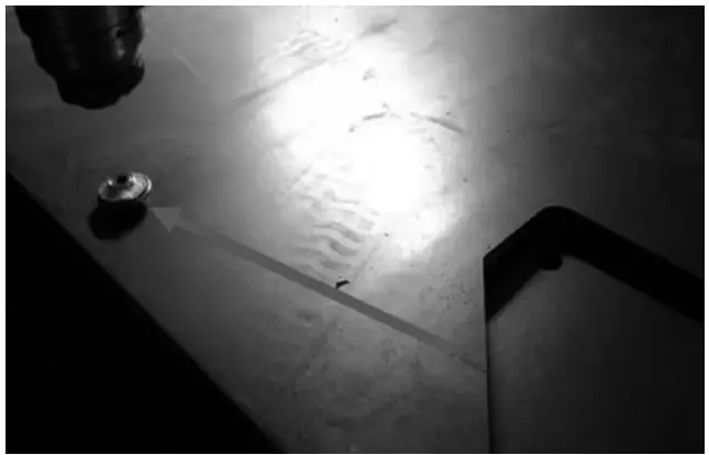
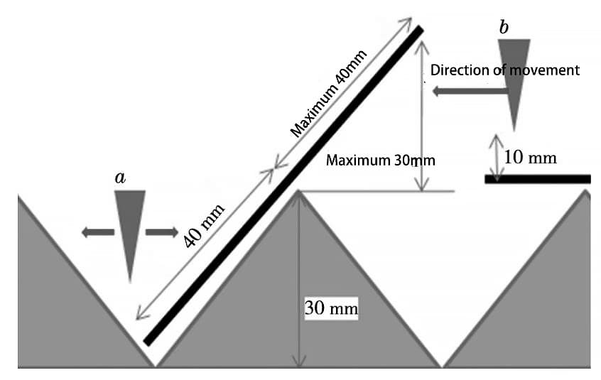
(2) According to the photos of the collision scene taken by the operator (Figure 3), a numerical model (Figure 4) is established to analyze the occurrence of collisions: the collision will occur when the point moves in any direction, and the collision will occur when point b moves to the left.
(3) According to the numerical model, the calculation shows that the maximum lifting or sinking height of the part is 30mm, and the lifting height is set at 10mm, which cannot completely avoid collisions. However, currently this control method cannot set the lifting height to more than 10 mm.
2.6 Corrective and Preventive Measures
(1) Develop an adjustment plan. Adjust Machine #1 subroutine, delete Z axis movement to 10mm sensor detection position and change it to: Z axis moves 35mm in negative direction, no longer uses follower control of the sensor and works without abnormalities during the test run. After 24 hours of continuous operation without collisions or abnormalities, adjust the program for Machine #2.
(2) Validate feasibility. Record the load rate of the Z axis servo motor before and after adjustment, the maximum difference of the load rate before and after adjustment is very small, and both do not exceed 30%.
(3) Verification. It has been running continuously to date (4 months) with no crashes or abnormalities.
Conclusion
The “high voltage drop” fault and cutting head collision of CO2 laser cutting machine seriously affect production efficiency and cause substantial losses. By analyzing the cause of failure, ruling out failures, identifying the real cause and implementing corrective and preventive measures, similar failures are completely avoided. By studying the structure and principle of the equipment, and summarizing the repair experiences, we have achieved autonomous repair of some faults of these equipment.


