Bending Accuracy
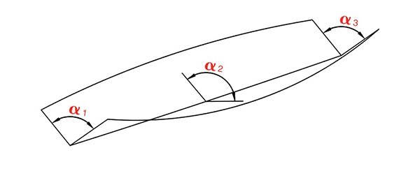
Angle error and straightness error

Question: Is there an angle error and a straightness error in the “ideal bending state”?
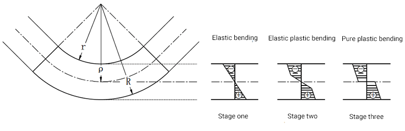
Stress and strain analysis of sheet metal bending process
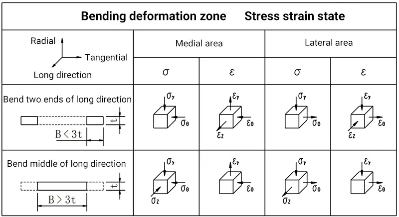
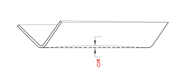
Straightness error analysis
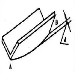
After bending the sheet metal, the edge of the bent part will exhibit natural deflection, which is normally measured by its maximum deflection (δ).
According to the stress analysis, the stress (σZ) in the deformation zone is externally tensile and internally compressive. These opposing tensile and compressive stresses create a bending moment, which is necessary to keep the part straight during bending. However, at the end of the bending process, this moment disappears, causing the piece to deflect upwards.
The longer the bending plate, the greater the deflection (δ). Similarly, the wider the bent plate, the smaller the width of the plate, the greater the deflection (δ).
However, reducing the bend angle from 150° to 90° will reduce the deflection (δ).
Furthermore, as the plate thickness increases, the deflection (δ) will increase proportionally.
Applying pressure to the edge of the folded sheet, such as through patch bending or three-point bending, can improve the straightness of the workpiece.
Factors Affecting Bending Accuracy
The main factors that influence the bending accuracy of a bending machine are the rigidity of the bending machine, the bending mode and the bending force.
1 . Press brake stiffness
How to determine the stiffness index of the bending machine in the project?
Deflection deformation of press brake machine
2. Push-up mode
1)Airbending
2) Three-point push-up
3) Coinage
3. Bending strength
How does bending force change during bending?
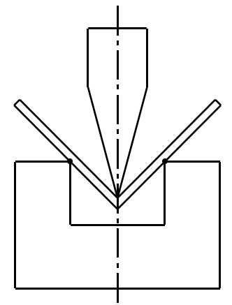
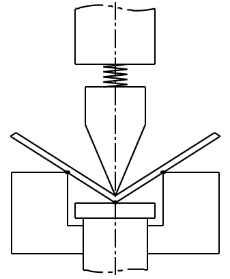
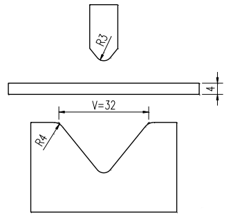
1) Free flexion of the sharp punch
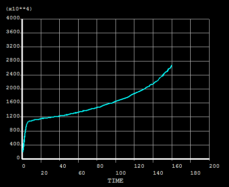
As illustrated in the attached figure, in free bending mode, the sheet material is made of Q235 steel, which is considered to have ideal elastic-plastic behavior with linear hardening. The yield strength of this material is σS = 250 MPa, and its hardening modulus (also known as tangent modulus) is 1050 MPa.
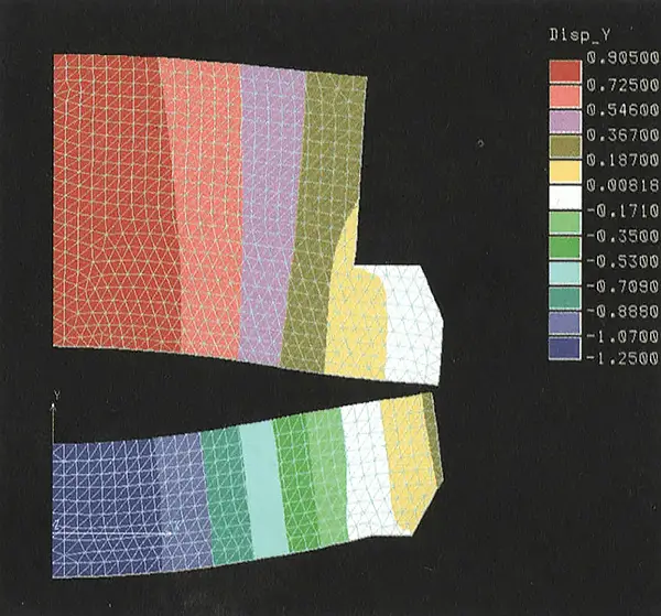
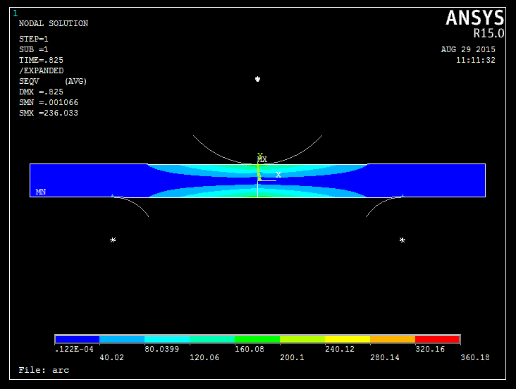
The ANSYS analysis results are as follows
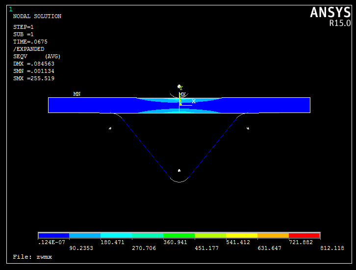
Bending force curve:
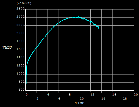
The results of the analytical method are as follows
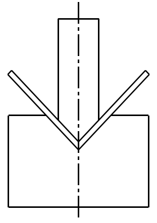
2) Wide knife folding
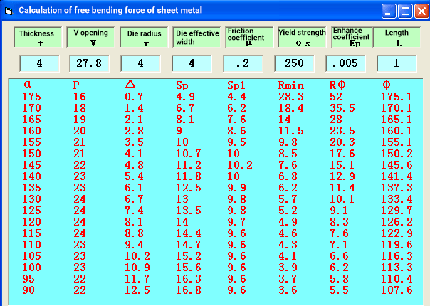
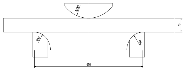
As illustrated in the attached figure, the upper die is designed with a wide arc R180, and the sheet material is set to X80. This material has ideal elastic-plastic behavior with linear hardening and its yield point is σs = 552 MPa. The hardening modulus (also known as tangent modulus) of this material is 840 MPa.
The ANSYS analysis results are as follows
Bending force curve:
There are other factors that affect the bending accuracy, among which are the uneven thickness of the plate, the hardness of the plate, the deformation of the bench and ram during bending, the selection of the die opening, the depth of the upper die in the die bottom, the wear of the matrix and the convexity of the bench. These factors can cause errors in the bending angle and straightness of the part after bending.
The die opening and the depth of the upper die into the lower die are controlled by manual programming.
4. Influence of material quality on accuracy
The nominal bend is a free bend of low carbon steel sheet with tensile strength σb = 450 N/mm², which bends the sheet at an angle of 90° into the V-shaped die with an opening distance V = 8 × S.
When nominal bending is performed with plates of uneven thickness, angle errors may occur.
When the hardness of the plate is not uniform, the elastic return of the part during bending is not equal.
Therefore, the quality of materials has a significant impact on the quality of processing.
5. Convex compensation of the work table
Under the action of the load, the bench and ram will undergo elastic deformation.
The depth of the upper die into the lower die is uneven along the entire length, which may affect the bending angle and straightness of the workpiece.
To solve this problem, the machine adopts the convex NC of the worktable to compensate its deformation, keep the depth of the upper die into the lower die essentially uniform along the entire length, and improve the accuracy of the bending angle and straightness of the workpiece. of work.
6. Eccentric loading
Eccentric loading refers to the loading operation on the left or right side of the ram. The machine has a strong ability to resist eccentric loads.
Under the action of the eccentric load force, inclination will be generated between the bench and the ram.
The grid detection mechanism at both ends of the ram will detect the deviation and provide feedback to the computer. The computer controls the proportional servo valve to adjust the amount of oil entering the oil cylinder, to keep the position of the two pistons synchronized and maintain a small parallelism error between the bench and the ram.
When processing special parts, the above eccentric load must be considered. In general, it is necessary to avoid operating under eccentric load.
7. Bending angle error correction
After the bent part has been formed and the angle is about α°, the error value of the measured angle △α° can be corrected by adjusting the Y position of the bottom dead center. The correction value △Y can be calculated approximately according to the following formula: △Y = K × V × △α
Where:
- △ Y – bottom dead center correction value (mm)
- V – selected die opening (mm)
- △ α – Angle error value (degrees)
- K – Correction factor (degree /mm)
When α ≈ 90°, K ≈ 0.0055; for 8-12 sided bent steel bar, when α ≈ 135°-157.5°, K ≈ 0.004.
If the angle of the inspected part is greater than the drawing requirements, adjust the bottom dead center position downward according to the △Y correction value; otherwise, adjust upward.
Example 1:
The angles at both ends are equal to the mean angle.
To bend a dodecagon with α= 150°, select the opening V = 200mm, and measure the angle after bending, α= 151.5°. Using the above method, △α is calculated as 1.5° and K is 0.004.
△Y = K × V × △α = 0.004 × 200 × 1.5 = 1.2 mm.
Enter the bottom dead center position Y + △Y into the computer.
Example 2:
The angles at both ends are not equal to the mean angle.
For a part bent at α=90° with opening V = 60mm, the actual angles measured at both ends are α=90°, and the average angle is α=91° (the convex quantity is not enough).
Using the method above: △α = 1°; K=0.0055
△Y = K × V × △α = 0.0055 × 60 × 1 = 0.33 mm.
Add △Y to the original convex value and enter it into the computer.
If the average angle is smaller than the angles at both ends (the convex amount is too large), reduce the convex value by △Y from the original base and enter it into the computer.
Example 3:
The angles at the lower ends of the column are not equal. With opening width V = 60mm, a part is bent at α = 90°.
The actual angle measured at the left end is α=90°, and the angle at the right end is α=91° (bottom left and top right).
Using the above method: △α=1, K=0.0055
△Y=K × V × △α=0.0055 × 60 × 1=0.33 mm
Enter the Y + △Y value at the right-most zero point upwards to change its reference position.
8. Angle Accuracy
Angle accuracy is arguably the most complex and challenging parameter to control in bending operations. There are two common bending methods: bottom bending and air bending. Various applications of bottom bending are illustrated below.
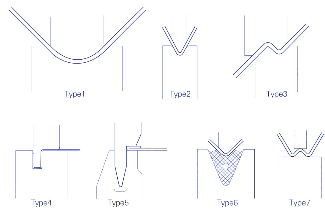
Bottom bending is controlled by adjusting the downward force applied during the bending process to shape the metal. Its advantages include high angular accuracy, reaching up to ±15 minutes, with consistent bend angles.
However, the disadvantages are significant: it requires up to five to eight times more force than air bending and has less flexibility. Different angles or shapes require different tools.
Air bending, also known as free bending, is most commonly used. It is controlled by regulating the descent of the Y axis, i.e. the depth to which the upper die penetrates the lower die, thus controlling the bending angle.
The advantages of air bending include less force required and high flexibility, as one set of tools can bend parts at multiple angles. The disadvantage is less precision in the angle of the bent part and less consistency.
Why is the angle accuracy of air bent parts lower? For example, when bending sheet metal with a V10 lower die, a 0.05mm difference in the distance the upper die presses can result in an angular deviation of 1°, as shown in the table below.
Table: Changes in descent depth corresponding to a 1° angle variation for different die bottom openings and bend angles
| Mold bottom bending/opening angle | 30° | 45° | 60° | 75° | 90° | 105° | 120° | 135° | 150° | 165° |
| 4 | 0.17 | 0.07 | 0.04 | 0.03 | 0.02 | 0.02 | 0.02 | 0.01 | 0.01 | 0.01 |
| 6 | 0.26 | 0.11 | 0.07 | 0.05 | 0.04 | 0.03 | 0.03 | 0.03 | 0.03 | 0.03 |
| 8 | 0.36 | 0.14 | 0.08 | 0.06 | 0.05 | 0.04 | 0.04 | 0.03 | 0.03 | 0.03 |
| 9 | 0.41 | 0.16 | 0.09 | 0.07 | 0.05 | 0.05 | 0.05 | 0.04 | 0.03 | 0.03 |
| 10 | 0.45 | 0.18 | 0.10 | 0.08 | 0.05 | 0.05 | 0.05 | 0.05 | 0.05 | 0.04 |
| 12 | 0.54 | 0.22 | 0.13 | 0.08 | 0.07 | 0.05 | 0.05 | 0.05 | 0.05 | 0.05 |
| 14 | 0.61 | 0.24 | 0.15 | 0.10 | 0.08 | 0.07 | 0.06 | 0.06 | 0.06 | 0.06 |
| 15 | 0.66 | 0.26 | 0.16 | 0.11 | 0.08 | 0.08 | 0.07 | 0.07 | 0.07 | 0.06 |
| 16 | 0.71 | 0.28 | 0.16 | 0.12 | 0.09 | 0.08 | 0.07 | 0.07 | 0.07 | 0.07 |
| 18 | 0.81 | 0.32 | 0.19 | 0.13 | 0.11 | 0.09 | 0.08 | 0.08 | 0.07 | 0.07 |
| 20 | 0.90 | 0.36 | 0.21 | 0.15 | 0.11 | 0.10 | 0.09 | 0.09 | 0.09 | 0.08 |
| 22 | 1.00 | 0.40 | 0.23 | 0.16 | 0.13 | 0.11 | 0.10 | 0.09 | 0.09 | 0.09 |
| 24 | 1.09 | 0.44 | 0.25 | 0.17 | 0.14 | 0.11 | 0.10 | 0.10 | 0.10 | 0.10 |
At present, the Y-axis accuracy of press brakes can generally reach 0.01mm, so the angle deviation should not be too severe. But can sheet metal thickness be guaranteed to be perfectly consistent?
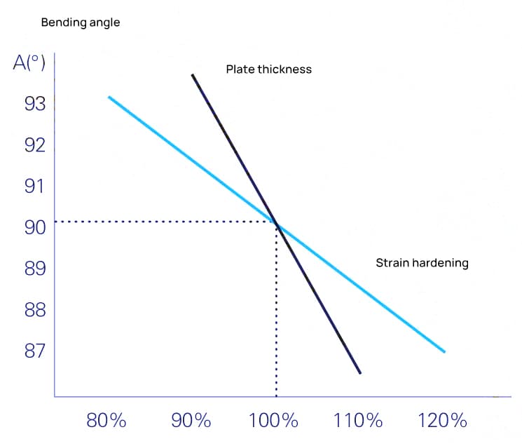
If a 1.5 mm thick sheet varies by 10% in thickness, this represents a difference of 0.15 mm, equivalent to a difference of 0.15 mm in the distance between the upper and lower dies, resulting in an angular deviation of approximately 3°.
Likewise, a 10% change in the strain hardening characteristics of sheet metal can cause about a 1.5° change in the bending angle. The impact of sheet metal thickness and strain hardening on the bending angle during air bending is shown in Figure 6.
This is where bending machines differ from metal cutting machine tools. With metal cutting machines, regardless of the size differences between the raw parts, the final accuracy of the machined parts can be guaranteed as long as the machine tool is sufficiently precise.
However, this is not the case with the common practice of air bending in press brakes; It's not a question of the machine's inherent precision.