During the working process, the positions of the top dead center, speed change point and bottom dead center of the CNC press brake must be adjusted according to the process requirements for bending the workpiece. The working pressure of the hydraulic system must also be adjusted according to the actual bending force.
Course adjustment
Top dead center adjustment
The top dead center position can be adjusted by programming the “opening” item on the controller to change the top and bottom positions. See “CNC System Operation Manual” for details.
Variable speed point adjustment
The variable speed point is the position of the ram when it changes from no-load speed to working speed. The position of the shift point can be adjusted by programming the “shift point” item on the controller.
Bottom dead center adjustment
After the ram completes the working stroke, the bottom dead center position can be adjusted by programming the “Y axis value” item on the controller.
Adjusting the working pressure of the hydraulic system
The pressure required for bending can be calculated using the table look-up method or formula method, and the table look-up method is preferred.
Calculation of pressure by the formula method
The required bending pressure can be calculated from the following bending formula:
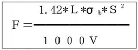
Where:
- F – load (KN)
- S – plate thickness (mm)
- L – flexion length (m)
- V – opening distance (m)
- σ b – tensile strength (N/mm²)
The new international standard unit of force is Newton.
- 1kgf ≈ 10N
- 1tf ≈ 10000N=10kN
- 1MPa ≈ 10bar
For example:
Plate material: 16Mn, σ b = 530N/mm², plate thickness: S = 15mm, plate length: L = 10000mm = 10m
Lower die opening distance: V = 8 × S = 8 × 15 = 120 mm
Calculated bending force F1 = 1.42×10000×530×15²/(1000×120) ≈ 14000 (KN)
Considering the influence of various factors, a reserve of 10% will be added to calculate the bending force.
Therefore, F2=1.1 × F1 = 1.1 × 14000=15400(kN)
Pressure calculation by table lookup method
The bending pressure table is shown in the figure below.
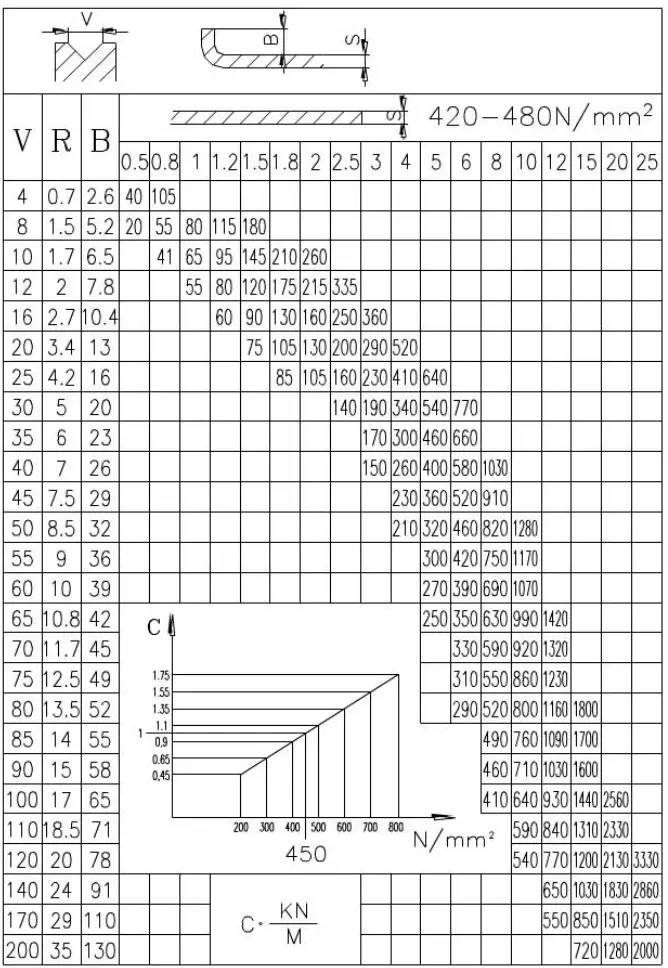
The value of the bending force in the table is given when σ b = 450N/mm², and its unit is KN/m.
On the table,
- S – plate thickness (mm)
- V – lower die opening width (mm, 8 × plate thickness)
You can use the bending pressure table to determine the required bending pressure.
For example:
It can be seen from the table that at the intersection of the plate thickness S = 15mm and the opening distance V = 120mm, the bending force per meter is F3 = 1200kN/m
As σ b = 530N/mm², check table C ≈ 1.18. (530/450≈1.18)
Calculate the bending force: F1=F3 × L × C=1200 × 10 × 1.18 ≈ 14000 (kN)
The required bending force will be calculated by adding 10% reserve.
Therefore, the required bending force: F2=1.1 × F1=1.1 × 14000=15400 (kN)
Working pressure adjustment
If the calculated bending force F2 of a bending length is less than the machine output force P in the table above, the working pressure of the hydraulic system should be reduced to reduce the oil temperature and improve the service life of the hydraulic components .
The working pressure Q of the hydraulic system can be calculated by the following formula:
Q=28 × F2/P(MPa)
The working pressure of the hydraulic system can be adjusted by the machine tool controller.
During adjustment, check the corresponding P value in the bending pressure table according to the actual bending force and input it into the computer.
Convex working table quantity
The bench and ram are supported at two points along the entire length.
Under the action of the load force P, deformation will occur, and the amount of deformation is represented by f (see the figure below).
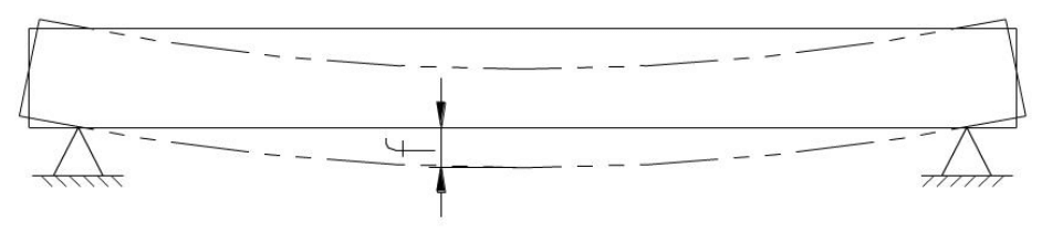
To solve this problem, the machine adopts a movable “convex” on the worktable to compensate for the deformation of the worktable and ram and improve the angle accuracy and straightness of the workpiece.
The adjustable convex amount of the working table ranges from 0 to 2.0mm.
During operation, determine the convex value according to the actual bending load force (or the angular difference between the two ends of the workpiece and the middle), and then input it into the controller for operation.
There is a small hole and a set of numbers on the end of the convex adjustment motor, which serve as reference positions of the measuring hole and the convex zero point, respectively. They provide convenience for users to determine the convex zero point.