As one of the most widely used sheet metal bending equipment, the CNC press brake is widely used in the sheet metal processing and equipment manufacturing industry. It is a crucial supporting equipment for sheet metal processing along with CNC turret punch, CNC sheet metal cutting machine and CNC laser cutting machine.
The CNC press brake works by using a simple general die and repeatedly moving the ram to bend the sheet into a variety of complex cross-sectional shapes. With the advancement of new technologies such as CNC, servo and die, CNC press brake technology is mainly focused on energy saving and high efficiency.
Furthermore, with the continuous improvement of bending accuracy and efficiency, various functional components are becoming increasingly available. Some companies with strong research and development capabilities are focusing on the design of various functional components, striving to improve the degree of automation in machine tools.
Among all the functional parts, the upper die quick clamping device has the most significant impact on the bending accuracy and efficiency, particularly in the production of bends of multiple varieties and in small batches, where improving the efficiency of die changing is particularly important. remarkable.
This article introduces two new upper die clamping devices that are easy to operate, energy-saving and efficient. The technical principle, mechanism design, technical characteristics and work process are described in detail.
1. Introduction of traditional fixture technology
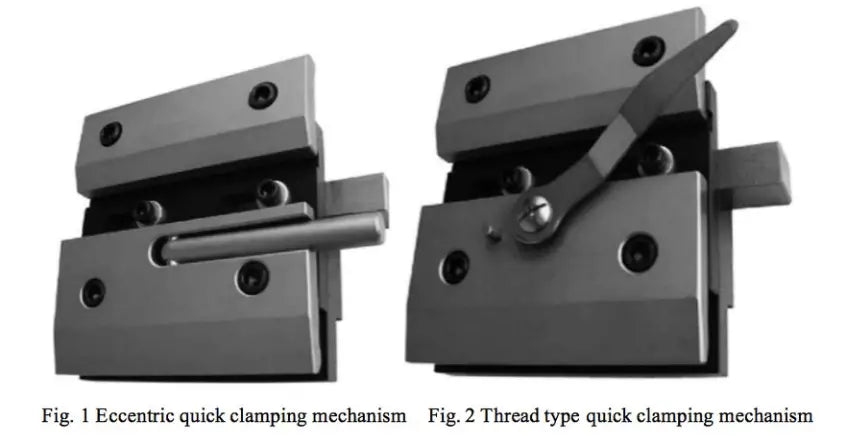
The upper die clamping device of China CNC press brake generally adopts mechanical structure, as shown in Fig.
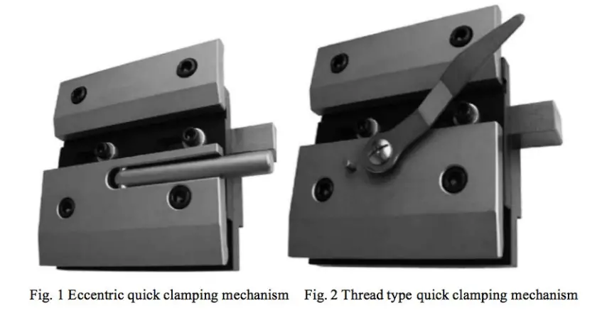
The eccentric quick clamp mechanism shown in Fig. 1 is characterized by having a cam rod at the end of the operating lever. The operating lever is firmly fixed to the front fixing block through a cylindrical pin, and a spring is fixed between the front fixing block and the fixed block.
To quickly clamp the upper die of the press brake, the upper die must be inserted into the side of the quick clamping device. The die can be quickly fixed by rotating the operating lever.
When the operating lever is rotated in the reverse direction, the front clamping block is quickly reset by the spring between the front clamping block and the fixed block, releasing the die and allowing it to be transported sideways.
The device is easy to use and operate, but has some limitations, such as uneven clamping force and the need to insert the matrix laterally.
Figure 2 shows a threaded quick clamp mechanism. To quickly clamp the press brake die, the upper die must be inserted into the side of the quick clamping device.
The operating lever is rotated to actuate the screw, which in turn actuates the front clamping block to advance and clamp the die. When the handle is rotated in the reverse direction, the front clamping block moves backwards, driven by the screw, to release the die and transport it sideways.
This structure offers the advantages of strong clamping force, good self-locking capabilities and simple operation. However, it has some limitations such as uneven clamping force and slower clamping speed.
2. Automatic hydraulic clamping device design
2.1 Schematic design
In this paper, two solutions are proposed to address the stress situation and size of the press brake upper die, based on the characteristics of the automatic hydraulic clamping device for the press brake upper die.
Scheme 1:
The matrix is held in place by the expansion force generated when pressurized oil is injected into the compressed rubber hose.
Both ends of the clamping device are equipped with a safety lock.
When the upper die is fixed, the safety pin of the safety lock is inserted into the hole of the die.
When the internal pressure of the rubber hose dissipates, the operator and die are effectively protected.
The automatic hydraulic clamping device is ideal for large-scale forming dies, such as those used in the automobile industry to press arch-shaped doors and windows.
Scheme 2:
The force generated by the compression hose is also used to extrude the die.
Furthermore, the automatic hydraulic clamping device is equipped with a mechanism to compensate for the deflection of the upper die and a safety locking mechanism.
The upper wedge of the deflection compensation mechanism can be adjusted to extrude the upper pin, thus compensating for any deflection in the upper die.
The safety pin on the safety locking structure provides effective protection for both the operator and the upper die.
This automatic hydraulic clamping device is suitable for use with standard dies and can accommodate segmented dies.
2.2 Structural design
According to the design idea of Scheme 1, the upper die automatic hydraulic clamping device shown in Fig. 3 and Fig. 4 can be obtained.
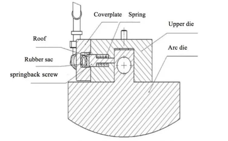
Fig. 3 Scheme 1: Hydraulic automatic clamping mechanism of the upper matrix
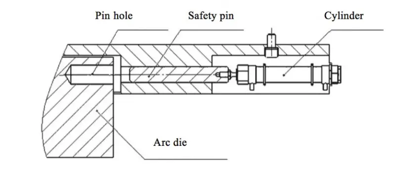
Fig. 4 Safety lock mechanism
The automatic hydraulic clamping device for the upper die is composed of a clamping mechanism and a safety locking mechanism. The components of the clamping mechanism include the upper die base, rebound screw, top plate, spring, cover plate, rubber bag, follow-up hose, transition joint and plug.
The upper base of the die is securely fixed to the lower part of the sliding block using screws. The upper die seat has a vertical groove to hold the upper die handle and several parallel countersunk holes on one side. Recovery screws for extrusion dies and spring reset springs are placed in these countersunk holes.
The cover plate is attached to the side of the upper die base and has a through groove. A top plate and rubber tube are inserted through this groove, with the top plate positioned between the rebound screw and the rubber tube. The hose becomes compressed when not in use.
As shown in Fig. 4, a safety lock mechanism is located on both sides of the clamping device and consists of an air cylinder and a safety pin. The holes are positioned on the left and right sides of the upper seat of the die and press brake.
When the upper die is clamped, the cylinder pushes the safety pin through the hole in the upper die seat and into the hole in the upper die to ensure that the upper die remains suspended in the upper die seat groove even if the pressure inner part of the rubber hose falls off suddenly. This guarantees the safety of the operator and the matrix.
Following the design concept of scheme 2, a second hydraulic automatic clamping device for the upper die can be produced, as shown in Figures 5, 6 and 7.
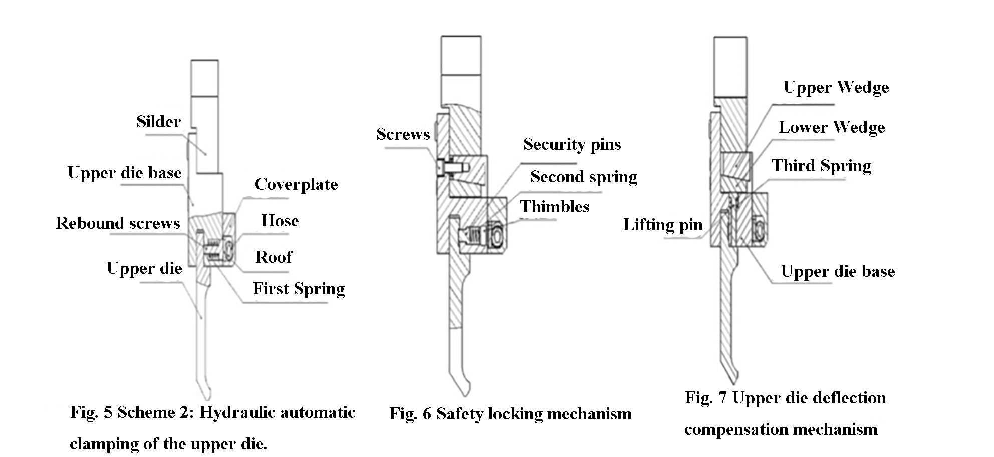
The schematic diagram of the upper die automatic hydraulic clamping device reveals that it comprises a clamping mechanism, a deflection compensation mechanism and a safety locking mechanism.
The device consists of a first cover plate, a clamping head, a top plate, a rubber tube and a clamping head.
The lower part of the sliding block is fixed to the upper base of the die with screws.
The upper base of the die has a horizontal groove at the bottom and a first countersunk hole on the side.
The first countersunk hole is equipped with a first spring, which is placed on the surface of the springback screw.
The springback screw passes through the first countersunk hole and interacts with the upper die handle of the press brake.
The through tube has one end equipped with a through tube, while one end of the rubber tube is connected to the rubber bag.
A ceiling is positioned between the hose and the spring-back screw.
In its initial state, the hose is compressed by the preload of the first spring.
The device shown in Fig. 6 includes a safety locking mechanism consisting of a safety pin, a jack screw, and a second spring. The mechanism is designed to ensure operator and die safety should the clamping mechanism stop working.
The side of the upper base of the die is equipped with several second countersunk holes. One end of these holes is connected to the horizontal groove, while the other end is threaded. The safety pin passes through the second countersunk hole and engages the groove in the press brake's upper die. The preload of the second spring can be adjusted by rotating the upper screw, which regulates the extrusion force between the safety pin and the upper die.
In addition to the safety locking mechanism, the device also includes an upper die deflection compensation mechanism, as shown in Fig. 7. This mechanism consists of several upper wedges, lower wedges, lifting pins, groups of disc springs, and a third spring.
The top of the die's upper base features multiple slots, each equipped with two third countersunk holes. One end of the third countersunk holes is connected to the bottom of the upper die base. The upper and lower wedges are installed in the groove of the upper die base and connected to it using screws. A group of disc springs is positioned between the upper wedge and the upper base of the die.
A third spring is placed on the surface of the ejector pin and installed in the third countersunk hole. The ejector pin engages the upper die of the press brake through this hole.
2.3 Technical characteristics
- The hydraulic automatic clamping device presented in this article is more superior to the mechanical clamping device. It not only provides automation but also allows for simpler operation. The die can be conveniently inserted into the groove of the upper die seat.
- The clamping device in this article uses hydraulic clamping, which allows precise adjustment of clamping force and uniform distribution. This results in greater reliability.
- The device is also equipped with a safety mechanism to protect the operator and the die.
- Rubber tube expansion extrusion die is adopted for the clamping device in this article, providing simple structure, cost-effectiveness and practicality.
- In Scheme 2, the clamping device is equipped with a deflection compensation mechanism to effectively improve the bending accuracy.
- In Scheme 2, the upper die of the press brake can be segmented, allowing the assembly of different upper dies on the press brake.
2.4 Movement process
Scheme 1:
The first step in using a press brake is to place the upper die into the lower die of the worktable, either through manual operation or with the help of a manipulator. The sliding block then causes the upper seat of the die to move downward.
Then the upper handle of the die is inserted into the groove of the upper base of the die and the sliding block moves to the bottom dead center. The relevant hydraulic system is then activated.
Oil under pressure enters the rubber stamping tube, causing the tube to expand and extrude the top plate and cover plate. As the cover plate is attached to the top base of the die, extrusion of the roof causes the rear spring bolt to extend, which in turn secures the top handle of the die and spring.
The cylinder in the safety locking mechanism pushes the safety pin into the hole in the upper seat of the die and enters the hole in the press brake machine. During the bending process, if the middle pin is pressed, the security die is removed from the air cylinder.
Once bending is complete, the pre-tightening force of the spring ejects the springback screw, releasing the upper die from the machine. The matrix can then be changed manually or with the help of the manipulator.
Scheme 2:
When operating the device, first insert the upper die handle of the press brake into the groove of the upper die base manually or with the help of a manipulator. Overcome the preload of the second spring by sliding the top handle of the die along the beveled edge of the safety pin on the safety device.
After the upper die handle has been fully inserted into the upper die base groove, press the safety pin into the upper die groove of the press brake. The safety locking mechanism will lock and secure the press brake's upper die in place.
The pretension force of the second spring can be adjusted by rotating the upper screw, thereby adjusting the extrusion force between the safety pin and the upper die of the press brake.
After all necessary upper dies have been placed in the device, close the upper and lower dies of the press brake and activate the relevant hydraulic system.
The pressurized oil will then flow into the inside of the rubber tube, causing it to expand and expel the top plate and cover plate. The cover plate and upper die seat are held in place by screws, so as the roof is extruded it also pushes against the rebound screw, which in turn compresses the first spring and secures the upper die of the bending machine.
At this point, the deflection compensation mechanism of the press brake's upper die can be used. To do this, adjust the position of the upper wedge by turning the second screw clockwise.
The upper wedge will then extrude the disc spring group and the lower wedge, causing the lower wedge to extrude the ejector pin. The ejector pin then compresses the second spring and upper die of the press brake, effectively compensating for any deflection of the upper die.
When the deflection compensation is canceled, turn the second screw counterclockwise and move the upper wedge backwards by the preload of the disc spring group.
The lifting pin and lower wedge are lifted by the preload of the second spring, causing the upper die deflection compensation to disappear.
When changing the die, first release the pressure from the rubber tube. The first spring will then eject the return screw through pre-tightening force, causing the rubber bag to flatten and releasing the upper die of the press brake.
Remove and replace the upper die of the press brake by manual operation or manipulation, overcoming the preload of the third spring.
3. Conclusion
The processing and manufacturing industry is developing rapidly and automation is improving rapidly, so the demand for efficient die changing in bending machines is growing. As a result, it is crucial to develop a quick clamping device for the upper die of bending machines.
Research into this technology not only advances die changing technology and increases efficiency, but also improves bending accuracy. When used appropriately, this technology can improve companies' competitiveness in the market and result in substantial economic benefits.