Lump forming is suitable for various types of blanks, such as stamped cups, cut tubes and rolled conical weldments.
Classification by lump-forming medium
Lump formation methods can be categorized as follows:
1) Hard matrix bulge formation.
2) Soft matrix bulge formation, also known as rubber bulge formation.
When rubber elastomers are used as a medium, they can be divided into those with and without matrix cavities. With die cavities, there are closed-loop and open-loop cavities. Closed-loop cavities are made from a single piece of material shaped into a closed curve by turning or milling. Open circuit cavities consist of multiple petals that are closed by external force before forming.
3) Hydraulic formation of protuberances.
4) Formation of low melting point alloy lumps.
This method uses a low-melting alloy as the medium, either by pouring the molten alloy directly into the tube or by inserting a central rod made of the alloy into the tube.
The process is essentially a radial extrusion of the entire blank. Its advantage is that it does not require sealing, but its disadvantages include inconvenient loading and cleaning and low production efficiency. It is suitable for materials with high strength or parts that require large deformation forces despite having low strength.
5) Other medium bulge formation methods, such as semi-fluid media such as paraffin, grease and petroleum jelly, are characterized by good sealing properties and the ability to generate uniform internal bulge pressures. They are virtually incompressible, but their disadvantages include the alternating heating and cooling processes required for charging and cleaning.
6) New processes such as lump forming with steel balls replacing soft or fluid molds, and explosive forming, as shown in Figure 6-2.
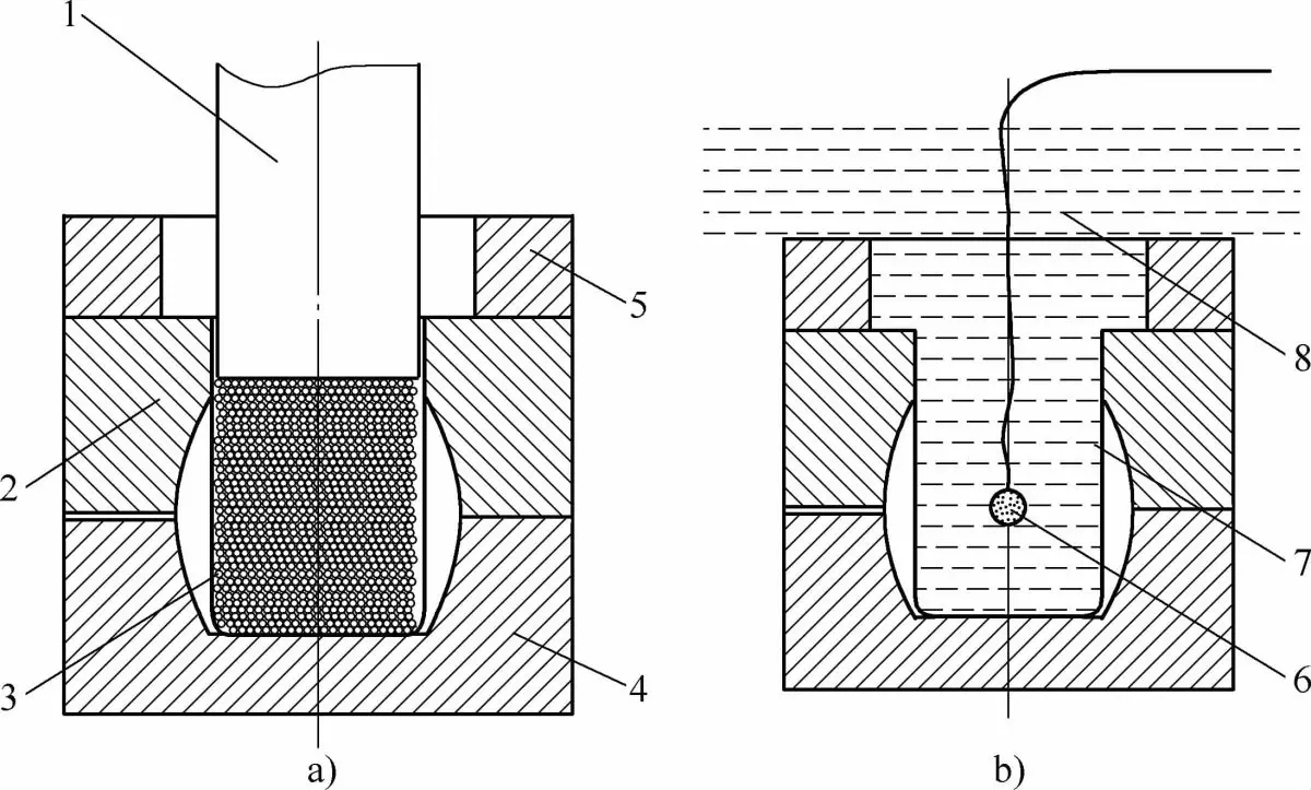
a) use a steel ball instead of a mold or soft fluid; b) explosive forming method consisting of 1 – male die, 2 – female die, 3 – steel ball, 4 – lower half of the female die, 5 – die ring, 6 – explosive, 7 – empty tube, 8 – water .
Classification by matrix structure
Bulge formation can also be divided into natural bulging and axial compression bulging based on the matrix structure.
(1) Natural bulge
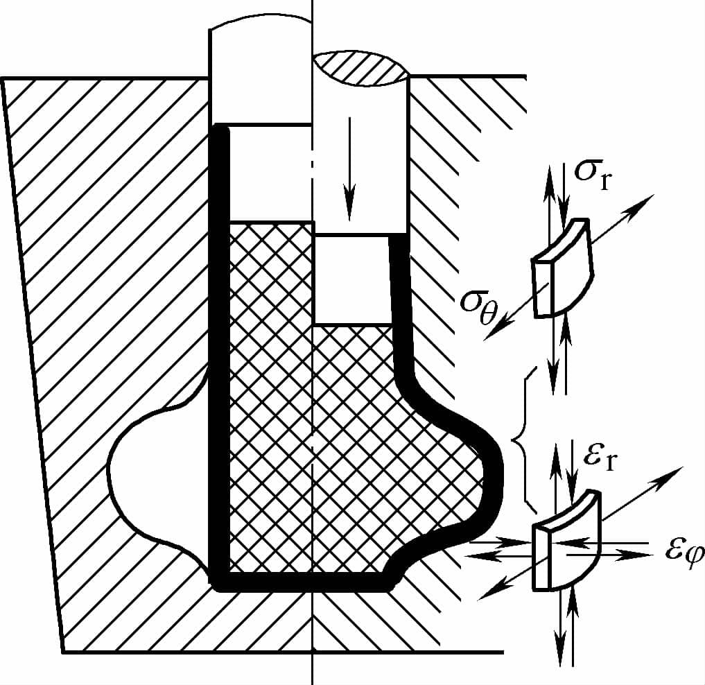
Natural bulging occurs when the part takes shape primarily through thinning of the raw wall and natural axial contraction (shortening). As shown in Figure 6-3, during natural bulging, the blank wall mainly bears biaxial tensile stresses in a plane stress state and deforms by thinning and stretching in two directions.
The deformation in natural bulging is quite complex, varying greatly with the shape of the bulging part and the location of the bulging due to the presence and magnitude of axial contraction during the process. The forming limit during shaping depends solely on the thinning of the void wall and is related to the material stretching rate and wall thickness. This type of forming, which depends entirely on thinning, is actually a form of localized forming.
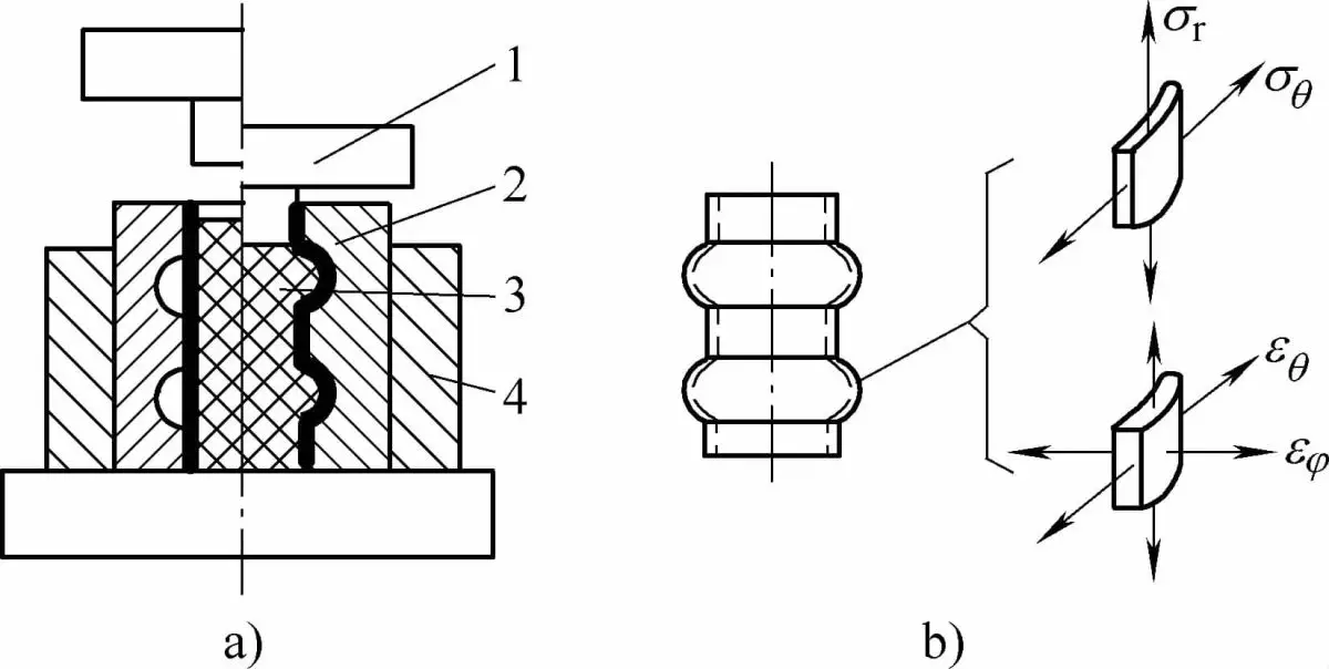
a) Bulging process b) Stress-strain state of the component.
1. Pressure head 2. Composite die 3. Rubber elastomer rod 4. Die holder.
(2) Axial compression bulging
Axial compression bulging, also known as plastic extrusion bulging, is accomplished by applying compressive force along the axis of the tube during bulging. In practice, axial compression is often used to increase the bulge factor and meet the forming limit of the material. The application of axial compression improves the state of stress and deformation in the bulging zone, facilitating plastic deformation.
For example, when the axial pressure is sufficiently high, the axial tensile stress in the deformation zone becomes compressive, resulting in a tensile and compressive stress state, and the deformation state can change from thinning in thickness and elongation in the radial and axial directions to axial compression and radial stretching, with little or no thinning in thickness, significantly increasing the bulge factor limit.
The axial compression force applied to the part and the bulging force exerted on the rubber matrix can be provided by the same component or separately by two or three components for bidirectional compression.
Depending on the magnitude of the axial compression force on the workpiece in relation to the bulging force on the rubber, as well as their relationship, the stress and deformation experienced by the material in the bulging region can vary significantly.
Normally, the axial stress in the tension state should be compressive, but if the pressure on the workpiece is insufficient, or the ratio between the pressure on the workpiece and the bulging force on the rubber is too low, a stress state of Traction may also develop.
This is essentially the same as natural bulging without axial compression. The deformation state should normally be a plane deformation state under tension and compression, or a volumetric deformation state under two-direction tension and compression, which must be carefully distinguished in the mold design for specific components.