Sheet metal flat patterns are an essential aspect of sheet metal processing. Today, we will discuss how to draw bend lines for CAD sheet metal flat patterns on sheet metal fabrication drawings.
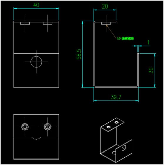
In the example below, we have a standard sheet metal fabrication CAD drawing of a component that we need to process. We must convert the orthographic views into a flat pattern, which is the sheet metal pattern.
To draw sheet metal bend lines, first determine the bend allowance of the sheet metal. The position of the bend line is determined based on the bend allowance. In the illustration below, the bend tolerance is calculated using the formula: inside dimension + inside dimension + compensation factor.
Related Reading: Curvature Tolerance Formula
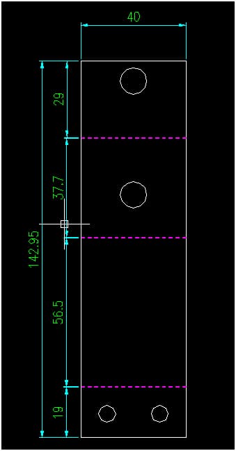
The thickness of the metal sheet is 1 millimeter and the compensation factor is 0.25. Determine this value, offset the bend size by subtracting 1 (sheet metal thickness) and then offset 0.25 (compensation factor). Continue offsetting adjacent bend sizes, and so on, until the final line segment.
Measure each value to ensure it conforms to the internal dimensions and compensation factor.
Modify the CAD line type to dashed lines and set the color according to your company's preferences or requirements.
At this point, the bend lines of the CAD sheet metal flat pattern are complete. Production workers can now process and bend sheet metal based on fabrication drawings.
The calculation of flexion margin varies between companies; the example above is just one approach.