
Bending forming is widely used in forming sheet metal parts. This method is characterized by high efficiency, high-quality results, saving time and costs when processing parts.
However, due to a lack of understanding of the bending process, process personnel often resort to traditional methods such as manual forming and hydraulic forming to obtain the final shape of parts.
These techniques increase the cost of processing parts through the use of forming tools, can result in unstable parts due to increased human involvement, and reduce machining efficiency.
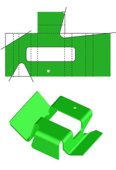
Fig.3 Simulation of punch bending and die combining
Figure 3 shows the material thickness of 1.6 mm for the simulated part, along with the bend radius R4 and a bend height of 8.9 mm.
After performing the analysis, it was discovered that the bottom slot of the die could be selected as V12 or a smaller option. However, for this specific part, only the V12 slot could be chosen. The reasoning for this is shown in the figure, with the V10 slot on the left and the V12 slot on the right.
Considering the resilience of the part during bending, the angle input to the press brake controller should be less than 90 degrees.
As seen in the simulation figure for the flange bent 90 degrees, if the press brake punch continues to move downward, the V10 groove will experience significant extrusion, while the V12 groove will experience minimal extrusion.
Therefore, it is recommended to select the lower die with V12 slot instead of V10 and smaller options. This will ensure that both sides of the bend radius remain free of indentations and will not require any finishing, resulting in a qualified part.
Technical analysis of typical bent parts
When bending parts, it is important to consider both the flange height and the web width. If the web width is too narrow and the flange height is too high, interference may occur between the previously formed flange and the bending tool during the bending process, preventing further bending.
This can result in the entire batch of material being discarded, leading to increased processing costs if no corrective action is taken.
In the following analysis, we will examine the bending of “U” shaped parts and “Z” shaped parts.
Related Reading: V and U Shaped Bending Strength Calculator
(1) Technical analysis of “U” shaped parts
The key factor in the bending of “U” shaped parts is the relationship between the height (H) of the two flanges and the width (B) of the web. If H is less than or equal to B, it is usually possible to bend the part, although interference may occur. This type of interference occurs between the part's bending flange and the machine body.
For a standard bending machine, if the bending height H is greater than or equal to 80 mm, the workpiece will interfere with the machine during the bending process.
When faced with such interference problems, there are two solutions:
- Before bending the part, create an obtuse angle at the web, opposite to the direction of the flange. This allows the part to avoid interference with the press brake during bending. After the flanges are bent to right angles on both sides, the obtuse angle on the web can be flattened using a hemming tool. However, this method may result in indentations at the bending position.
- For parts with a bending width of less than 200 mm, a special punch suspended in the upper die (as shown in Figure 4) can be selected for flange bending. The part flange is completely protected against die interference. This method is suitable for parts with a width of less than 200 mm due to limitations in the structure and strength of the upper die.
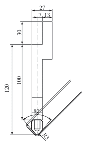
Fig.8 Post-processing status
(2) Another solution is to add a positioning auxiliary headset to the bent parts during blanking. The earpiece is at the highest level of the parts and can be used for positioning during bending and forming. After bending, the headset is removed to complete the bending of the parts. This greatly improves production efficiency.
(5) The parts broke at the bending point
When some parts break in the folded position, there are two main factors that can cause this:
- The material properties of the parts;
- The grain direction of the expanded material. To avoid breakage, the direction of the fibers of the expanded material can be changed so that they are perpendicular to the bending line, or an annealing process can be carried out on the bent pieces to make them more flexible.
Conclusion
The discussion and analysis of various situations encountered in the bending technique expanded the scope of the bending forming process in the production of sheet metal parts. This helps avoid errors in process selection that would negatively impact the overall part development cycle and improve production efficiency while stabilizing part quality.
The design of more reasonable bending tools will play a crucial role in expanding the application of bending forming technique.


