
Once the necessary tools have been identified, operators must define the correct bending sequence to obtain their product.
This is essential, as an error in the bending sequence can prevent the desired profile from being obtained, slow down the bending process or cause dimensional problems in the product if the countermeasures are poorly positioned.
It is not possible to define in a single article all the parameters to be considered to obtain the correct bending sequence, as the operator's experience plays an important role in finding the appropriate tools for the profile in question.
However, we can provide some useful tips. Let's dive into it.
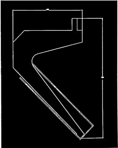
1. Especially for beginners, it is advisable to trace the bending sequence, modifying the sheet profile at each step.
2. To assess the possibility of collision between the profile and the tools, start by choosing the last bend and work backwards.
The last fold usually closes a profile and makes the other phases difficult to execute; For this reason, it is best to always start the sequence with the smallest folds closest to the edges of the sheet metal.
3. For a quick and efficient sequence, choose the sequence that requires the plate to be turned or rotated as little as possible.
Each of these actions involves wasted movements on the part of the operator.

5. Before performing the bend, simulate it graphically using the drawing in the catalog (there is usually a graduated scale at the bottom behind the tool) or a cutout of the tool.
If the operator has access to CAD or simulation software, he or she can use it to evaluate the viability of the profile, or the possibility of collisions between the sheet metal and tools or the press brake.
6. Identify a bending sequence that allows the operator to adequately support the sheet during bending and without risking safety.
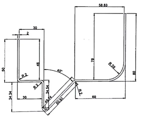
7. If a profile has obtuse angles or non-straight sides, work out the bending sequence so that the sheet is always positioned correctly against the back gauges.
This is very important to obtain a precise product with correct dimensions.
In fact, sometimes the positioning makes it impossible to be sure that the length of the curve at the end of the cycle is correct and in accordance with the measurement entered in the numerical control.
For this reason, the sequence must be configured so that the plate always touches the rear gauges on flat, straight surfaces.
To reduce production times, we recommend that designers avoid designing profiles with bearing surfaces that are not flat or have obtuse angles.
We also recommend they check:
- the type of back gauges available
- the number of the rear meters
- the maximum achievable height
- the minimum distance between two back gauges, as pressing the sheet metal against just one back gauge cannot guarantee accurate bending.
When thin sheet metal is being bent, it is recommended that it be supported on the back gauges and supported throughout the bending process to prevent it from arching and, therefore, modifying the X dimension; For this reason, the rear gauges have multiple supporting surfaces.

If an operator is unable to properly position the sheet metal against the back gauges, draw the bend line on the sheet metal with a marker and visually verify that all dimensions are correct.
In this case, it is important to ensure that the lines are the midpoint of the curve.
Press brake operators need clearly understandable drawings with all necessary dimensions.
If the operator is a beginner, designers should provide a three-dimensional view to help him; Furthermore, the dimensions drawn must be achievable, so it is best not to use too many decimal places or excessively tight tolerances.
8. Another fundamental factor in preparing the bending sequence is the tolerance of the profile dimensions.
Remember that during the bending process the numerical control measures the distances between the back gauges and the bend line, which is the punch contact point.
For this reason, the dimensions of some sides depend on previous folds.
For example, if we were to fold the drawing to the right, taking measurements A and C from the edges of the sheet, we would be sure that these dimensions were correct, while the middle section of 120 mm, that is, the remaining portion, would only be correct if the processing of the sheet was perfect.
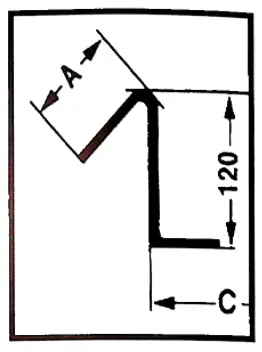
Therefore, it is recommended that the bending cycle be organized in such a way that measurements with close tolerances are always made directly from the point of contact with the back gauges and are never merely the result of other bends.
This way, potential defects can be restricted to non-critical sides. Designers must indicate to press brake operators which measurements are truly critical and which greater tolerances are permitted, significantly reducing assembly problems.
For more information on dimensional tolerances, read DIN 6935.
9. Back gauge configuration prevents dimensional defects, so press brake operators should regularly check the X-axis adjustment.
In addition to checking the part, operators must use a caliper to check the distance between the back gauge and the edge of the die, the shank width of which is known.


