
Press brakes are capable of accomplishing a lot, but there are still challenges involved in producing high-quality parts. In this discussion, we will explore the different types of push-ups.
To achieve a reproducible and reliable press brake process, it is necessary to have a combination of the press brake and its tools.
A press brake typically consists of two sturdy C-frames that form the sides of the machine, connected at the bottom by a massive table and at the top by a movable upper beam. However, the opposite configuration is also possible.
The lower tool rests on the table while the upper tool is fixed to the upper beam. In hydraulic press brakes, which are the majority of machines produced today, the upper beam moves through two synchronized hydraulic cylinders fixed to the C frames.
Press brake capabilities are defined by several characteristics, including pressure or tonnage, working length, distance to backgauge, working height, and stroke. The speed at which the upper beam operates typically varies from 1 to 15 mm/sec.
Increasingly, press brakes are equipped with computer-controlled multi-axis backgauges and mechanical and optical sensors to make adjustments during the bending process. These sensors measure the bending angle during the bending cycle and transmit real-time data to machine controls, which adjust process parameters accordingly.
Ultimately, press brake bending is a combination of factors involving the upper tool geometry (with punch angle and punch tip radius being the most important parameters), the lower tool geometry (particularly the width of the V opening, the angle V and the radii of curvature of the opening V) and the pressure force and speed of the press brake.
2 types of push-ups
Doubling
During the bending process, the longer leg of the sheet is clamped between two clamping beams. Then the bent beam rises and bends the extended part of the sheet around a bent profile, as shown in Figure 1.
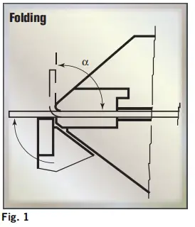
In modern bending machines, the bending beam is capable of forming both upward and downward, which is a significant advantage when creating complex parts with positive and negative bending angles.
The resulting bend angle is determined by the bend angle of the bent beam, tool geometry, and material properties.
Through-folding offers a significant advantage in that large sheets can be handled with relative ease, making this technique simple to automate. In addition, when bending, the risk of damage to the surface of the sheet metal is minimal.
However, a limiting factor of bending is that the movement of the curved beam requires sufficient space and processing time.
Cleaning up
During the cleaning process, the sheet is fixed again between the fixing beams. The tool then bends the protruding part of the sheet around the bend profile moving up and down, as shown in Figure 2.
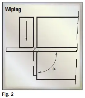
Compared to bending, cleaning is a faster technique for bending, but it also increases the risk of scratches or other damage to the sheet as the tool moves over the surface of the sheet. This risk is especially high if the bending involves acute angles.
Cleaning is commonly used to make panel-type products with small profiled edges. With special tools, this technique can be easily performed on press brakes.
4 push-up variations
When it comes to bending, there are four variations: air bending, laying, wedging, and three-point bending.
The characteristic of bending is that the sheet is pressed by an upper tool into the opening of the lower tool, as shown in Figure 3.
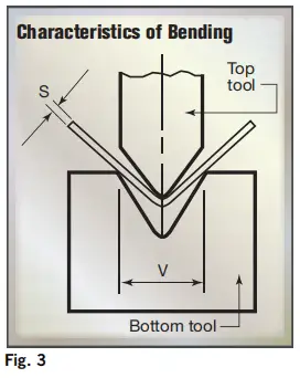
As a result of the bending process, the sheet metal on each side of the bend is lifted, which can cause problems such as sagging and folding, especially in large sheets.
In these cases, bending or cleaning is generally preferable, although sheet tracking supports can also be used with the press brake to alleviate these problems.
When bending involves both positive and negative angles, bending offers more flexibility than other techniques.
One of the significant advantages of using press brakes is the increased speed and flexibility they offer.
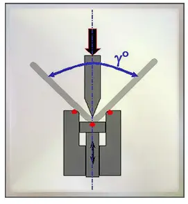
Air bending (partial bending)
Air bending is the most widely used type of bending thanks to significant improvements made to new bending machines, which offer better control of the springback of sheet metal.
This type of bend is used when there is air between the sheet and the V of the die. The name “partial bending” comes from the fact that the sheet metal comes into partial contact with the upper and lower tools, that is, at only three points during the bending procedure.
With air bending, the upper tool presses a sheet into the V-opening of the lower tool to a predetermined depth, but without touching the bottom of the tool, as shown in Figure 4.
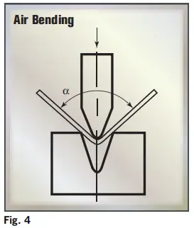
Air bending is a type of three-point bending, where only the bending radii of the upper and lower tools come into contact with the sheet metal. The punch radius of the upper tool and the V angle of the lower tool do not need to be the same. In some cases, a square opening replaces the V opening in the bottom tool, especially with today's adjustable bottom tools.
The combination of upper and lower tools can be applied universally, allowing the production of different products and profile shapes with a single combination, simply by adjusting the depth of the press stroke. In other words, a single combination of tools can be used to bend multiple materials and thicknesses at multiple bending angles, making air bending a highly flexible technique.
This also means that the number of tool changes required can be limited, greatly increasing productivity.
Air bending has another advantage: less bending force is required, allowing for smaller, less bulky tools and providing additional design flexibility.
However, a limitation of this technique is that it is less precise than processes where the sheet maintains full contact with the tool throughout the bending process. Stroke depth must be highly accurate and variations in sheet thickness and local wear on tools can result in unacceptable deviations.
Additionally, variations in material properties can affect the resulting bend angle due to springback.
Air bending requires a certain width for the V-shaped opening, which varies depending on the thickness of the sheet. For sheets with a thickness of up to 3 mm the value is 6 times the thickness of the material, while for sheets with a thickness greater than 10 mm the value is 12 times the thickness of the material. A rule of thumb is V = 8S.
Air bending provides angle accuracy of approximately ±0.5 degrees. However, the radius of curvature is not determined by the shape of the tool, but by the elasticity of the material. Typically, the bending radius is between 1S and 2S.
Due to its flexibility and low tonnage, air bending is becoming the preferred forming technique among manufacturers. However, variations in sheet thickness, local wear on upper and lower tools, and material properties can result in deviations in angle accuracy.
Special measures such as angle measuring systems, clamps, adjustable crowning systems along the X and Y axes, and wear-resistant tools can help solve these quality problems.
Benefits:
- Air bending allows the production of a wide range of angles using sharply angled tools. For example, you can use a 30° punch and a 30° die to bend profiles at any angle between 30° and 180°;
- Air bending is faster than other types of bending due to the shorter punch stroke;
- Springback is managed by taking the punch tip deeper into the V of the die and angle it closer rather than increasing bending force or stay;
- The required bending force is lower than other types of bending thanks to the option of choosing a wider die V;
- There are fewer marks on the sheet metal due to friction with the tools;
- Tools and press suffer less wear;
- Air bending allows the use of low force bending machines. Costs are lower and therefore air bending is an economical type of bending
Disadvantages:
- The angle accuracy with air bending is lower than with other types of bending. Tolerance is 3/4 of a degree (45′);
- The internal radius of curvature is not very accurate. In fact, the tip produces an ellipse;
- Because the sheet metal does not yield, the springback is greater and less predictable than with other types of bending. Therefore, the tool angle must be selected keeping in mind the need to go one degree or more beyond the required angle.
- If there are holes close to the fold line, they will be deformed.
Settlement
Bottoming is a variation of air bending that involves pressing a sheet against the slopes of the V-opening in the bottom tool (see Fig. 5), while allowing air to become trapped between the sheet and the bottom of the V-opening.
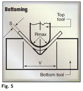
During seating, the punch hits the bottom of the V-die and presses the sheet metal against the sides of the die. This type of bending is suitable for precise profiles as its precision and consistency are higher than air bending.
The higher quality is due to the fact that during laying the sheet is pressed between the upper and lower tools and, therefore, the internal radius is concentrated in the bend area.
This results in a more precise radius, the metal sheet yields more and, consequently, the elastic return is lower.
Tool choice is critical for laying as operators need to identify the best angle for the punch and die and the expected springback to obtain the required profile angle. The punch and die must have the same angle to obtain a good bending result.
In this case, the radius of the punch and the angle of the V-opening are directly linked at the bottom, which means it does not offer the same flexibility as air bending.
Each bend angle and sheet thickness requires a separate tool set, and the same generally applies to different materials due to variations in springback and tool compensation required.
For the bottom, the ideal width of the V-opening (U-openings cannot be used) is 6S for sheets up to 3 mm thick, and increases to 12S for sheets over 12 mm thick.
Again, the rule of thumb is: V=8S.
The minimum acceptable bend radius for steel sheets ranges from 0.8S to 2S, although the quality of the material plays a role.
In the case of soft materials such as copper alloys, the radius of the bending angle can be much smaller, with a lower limit of 0.25S being possible.
When it comes to larger bend radii, laying requires approximately the same tonnage as air bending.
However, for smaller radii, laying requires a force that can be up to five times greater than air bending, which can lead to greater precision.
The resulting bend angle is entirely determined by the tool, except springback, which can be corrected.
It's worth noting that settling typically results in less springback than air bending.
In theory, laying can achieve angle accuracies as precise as ±0.25 degrees.
However, due to the increasing controllability and adjustability of press brakes, even on cheaper machines, air bending is becoming the preferred method when it comes to laying.
Benefits:
- Good accuracy using low force
- Good flexion repetition in the case of large production runs;
- Low elastic return
- If there are holes close to the bend line, they will be pressed between the tools during laying, so they will not be deformed as happens in air bending;
- Tolerance is about half a degree.
Disadvantages:
- Correcting the angle by moving the punch downwards is impossible, as the punch is already at the bottom in a V;
- Laying can only be used for curves with angles between 80° and 90°;
- Toolkits dedicated to a specific profile are required;
- The profile appearance is not that good.
Minting
People may find this name strange. Minting actually refers to the process of “punching metal coins,” in which each piece is identical to every other in shape and size.
For this reason, “coining” can be used in the bending process to indicate a method for consistently obtaining very accurate results.
Coining requires four to five times the force needed to bend air, and therefore a press brake and heavy tools are required.
When coining, the punch and the die must have the same angle required by the profile, therefore, in the case of a 90° bend, a 90° punch and a 90° die must be used without allowing elastic return.
The width of the die V is smaller for coining than for bottoming and air bending and should ideally be five times the thickness of the sheet metal.
This parameter prevents the punch tip from penetrating too much into the sheet metal due to the smaller internal radius.
Coining is not recommended for thicknesses greater than 2mm to avoid damage to the press brake, tools or sheet metal.
In coining, the upper tool crushes the sheet into the opening of the lower tool, all the way to the bottom of the V-shaped opening (see Fig. 6).

Coining requires significantly more force than bending and air settling, typically 5 to 10 times greater tonnage, and sometimes as much as 25 to 30 times greater. However, it offers the advantage of providing a high level of accuracy.
Due to the immense pressure applied by the punch tip to the material, permanent deformation occurs across the entire cross-section of the sheet, with elastic return practically eliminated. Because the angle of the punch and V-die are identical, the desired bend angle can be easily chosen, and variations in sheet thickness and material properties have little or no impact on coining results.
The high force and permanent deformation imply that the minimum achievable internal radius, starting at 0.4S, is smaller than with air and bottom, with the V-opening width typically requiring about 5S. A wider V opening would require a greater depth to achieve the same bending angle.
In general, coining is more expensive than air bending and laying and is therefore used sporadically, typically only for thin sheets.
Benefits:
- Consistent results
- Very narrow tolerance of an angle(1/4 degree)
- Possibility of bending metal sheets with large thickness tolerances
- The punch tip penetrates the material with high force and eliminates springback of the sheet metal:
- Possibility of obtaining very small radii (half the thickness of the sheet).
Disadvantages:
- Press the brake and the tools wear out quickly;
- Bad appearance of the plate;
- Only for angles up to 90°
- Not applicable for metal sheets thicker than 2mm.
Three-point push-up
The three-point push-up is a relatively new push-up technique that some consider a special variation of the air push-up.
This technique involves the use of a special die where the height of the lower tool can be precisely adjusted using a servo motor. The sheet curves along the radii of curvature of the die until it touches the bottom, with the angle of curvature decreasing as the depth of the bottom of the die increases.
The height of the lower die can be determined very accurately (±0.01 mm), with corrections made between the ram and the upper tool using a hydraulic pad to compensate for deviations in sheet thickness. As a result, the process can achieve bend angles with an accuracy of less than 0.25 degrees.
The advantages of three-point bending include high flexibility combined with high bending accuracy. However, obstacles include high costs and a limited range of available tools. Therefore, this technique is currently limited to highly demanding market niches, where the additional costs are offset by the declared advantages.


1comment
Gostei