A network of sensors is embedded in every vehicle, serving as a critical type of “nervous system” that detects and measures different automotive parameters. This network is essential for the safety, performance and efficiency of a vehicle. Various types of sensors are responsible for different functions, such as monitoring the temperature of engine components, vehicle speed for traction control, or proximity to objects for collision avoidance systems.
Data collected by these sensors is processed by the vehicle's electronic control units (ECUs) to make real-time decisions and adjustments, ensuring optimal operation. In this article, we will cover the many different types of sensors in modern vehicles and their critical role in providing a safe and enjoyable driving experience.
The role of automotive sensors
Automotive sensors collectively contribute to the operation of modern vehicles. Here are some of the attributes they offer.
Security
A vehicle's safety systems — such as stability control, traction control, and anti-lock braking system (ABS) — rely heavily on sensors. These systems modify engine power and braking to prevent skidding, loss of control and potential collisions using sensor data such as wheel speed, steering angle, etc. Within milliseconds, impact sensors identify collisions and initiate airbag deployment, protecting occupants from serious injury. Likewise, camera sensors help locate vehicles in the driver's blind area, which reduces the possibility of lane changes resulting in collisions.
Performance
Multiple sensors support automotive performance. For example, oxygen and mass airflow sensors are the reason a vehicle's engine can run smoothly and burn fuel as efficiently as possible. These sensors monitor engine temperature and air-fuel combination, optimizing performance and reducing emissions while improving fuel economy. Sensors that measure road speed and engine rpm also contribute to fuel economy and vehicle efficiency by ensuring the transmission shifts gears smoothly and effectively.
Additionally, radar and LiDAR sensors enable fuel-efficient cruise control on highways while ensuring a safe distance from other vehicles.
Predictive maintenance
Some sensors detect small anomalies in engine performance, tire pressure and other systems, alerting drivers to potential problems before they become more serious faults or defects. This often saves costs on repairs by allowing preventative maintenance.
Comfort and convenience
Enjoying the ideal temperature while driving is attributed to the vehicle's temperature and humidity sensors, which regulate the heating and air conditioning systems to maintain a comfortable cabin environment. Parking sensors can help drivers overcome obstacles and protect themselves from unintentional collisions. Light sensors improve safety and visibility at dawn and dusk by adjusting headlight brightness based on ambient light. Additionally, rain sensors automatically activate the windshield wipers, improving visibility in rainy conditions.
Driving alone
LiDAR, radar, cameras and ultrasonic sensors support autonomous vehicles by collecting environmental data and making safe navigation decisions. By detecting lane markings, roadblocks, pedestrians and other cars, these sensors help a vehicle make smart decisions and drive itself.
The sensors
Some of the most critical sensors are as follows.
1. Manifold Absolute Pressure (MAP) Sensor
2. Oxygen sensor
3. Mass Air Flow (MAF) Sensor
4. Crankshaft position sensor (CKP)
5. Camshaft position sensor (CMP)
6. Engine coolant temperature sensor
7. Engine oil pressure sensor
8. Throttle Position Sensor (TPS)
9. Knock sensor
10. Vehicle Speed Sensor (VSS)
11. Emission sensors
12. Steering angle sensor
13. Tire Pressure Monitoring System (TPMS) Sensors
14. Fuel level sensor
15. Lane departure warning system sensors
16. Voltage sensor
17. Convenience sensors
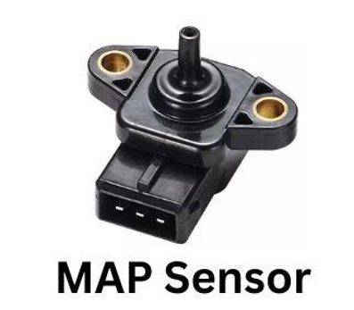
A multiple absolute pressure (MAP) sensor is a small but essential part of a vehicle's engine. It significantly impacts emissions, fuel economy and maintaining smooth, efficient engine operation. The intake manifold is the chamber where fuel and air mix before reaching the engine cylinders. As the name implies, MAP sensors detect the absolute pressure inside the manifold.
The Engine Control Unit (ECU) uses this pressure reading to calculate boost pressure, engine load and air density. The ECU uses pressure measurement to determine how much air enters the engine. This information is vital to figuring out how much fuel to inject for proper combustion.
Intake manifold pressure varies depending on how hard the driver presses the accelerator pedal. A higher pressure corresponds to a higher engine load, and the ECU modifies the ignition timing and fuel delivery accordingly. A MAP sensor monitors the pressure build-up produced by the turbo in vehicles equipped with turbochargers, allowing the ECU to regulate it for maximum efficiency and prevent excessive boost.
There are two main types of MAP sensors: piezoresistive and capacitive. Piezoresistive is the most common and uses a pressure-sensitive diaphragm that deflects slightly under pressure changes. This deflection changes the electrical resistance of a strain gauge in the diaphragm, which the ECU interprets as a pressure change.
Capacitive sensors use a small capacitor that detects changes in capacitance depending on the pressure applied to its diaphragm. The ECU measures this capacitance to determine the pressure.
MAP sensors have a sealed chamber with a reference pressure (typically atmospheric). Depending on the type of sensor, the intake manifold pressure acts on the diaphragm or capacitor plate. Deflection of the diaphragm or change in capacitance changes the electrical signal sent to the ECU. The ECU interprets the signal and uses it to calculate air density, engine load, or boost pressure. The ECU adjusts fuel injection, ignition timing, and other engine parameters based on these calculations.
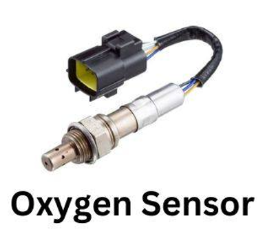
The oxygen sensor , sometimes called the O2 sensor, measures how much oxygen remains in the exhaust gases after combustion. The ECU regulates the amount of fuel and air entering the engine and depends on this data to stay in balance. The ideal air-fuel ratio is approximately 14.7:1, or 14.7 parts air for every part fuel.
By ensuring complete combustion, this ratio maximizes engine efficiency and reduces dangerous emissions. A key component in maintaining this delicate balance is the oxygen sensor.
Vehicles have two types of oxygen sensors: narrowband O2 sensors and wideband O2 sensors. Narrowband sensors are more common and less expensive. When the exhaust is high in oxygen (lean mixture), it produces a voltage signal that oscillates high (about 0.9 volts) and low (about 0.1 volts) when the exhaust is low in oxygen (rich mixture). . They cannot, however, continuously provide feedback on the precise air-fuel ratio and have a restricted response range.
Broadband sensors offer greater range and faster reaction than narrowband sensors, providing more accurate fuel changes. This is because the ECU continuously delivers the exact air-fuel ratio over a wider range of oxygen concentrations. The results are better engine performance, fewer emissions and greater fuel economy.
O2 sensors are located in the exhaust manifold and are exposed to exhaust gases. So, these sensors have a porous zirconia electrolyte layer and a ceramic housing. A voltage differential is created between the inner and outer electrodes due to oxygen molecules from the exhaust diffusing through the electrolyte layer. The oxygen content of the exhaust determines the voltage differential.
A low voltage indicates a rich mixture (not enough oxygen), while a high voltage indicates a lean mixture (too much oxygen). A reference voltage is sent to the sensor by the ECU. To obtain the ideal air-fuel ratio, the ECU compares the sensor voltage signal to the reference voltage and uses the difference to modify fuel injection.
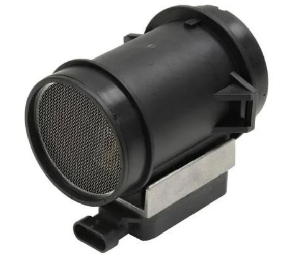
MAF sensor
The mass air flow (MAF) sensor measures the actual mass of air flowing into a vehicle's engine per unit of time, regardless of pressure or temperature. The ECU uses this data to calculate how much fuel to inject for complete combustion of the vehicle. For maximum performance and lowest emissions, an engine requires the ideal air-fuel ratio, or about 14.7 parts air to 1 part fuel.
While the MAF sensor measures the amount of air, the MAP sensor measures the air pressure. The MAF sensor is located in the intake pipe, before the throttle body, while the MAP sensor is located in the intake manifold, after the throttle body. The MAF sensor determines the air intake for fuel injection, while the MAP sensor determines the air density for fuel injection.
There are two types of MAF sensors: hot wire and film. The hot wire type uses a heated wire that cools as air flows over it. The sensor monitors the current required to maintain the temperature of the wire, proportional to the mass of air flowing. The amount of cooling depends on the airflow rate.
The film type uses a thin film heating element whose resistance varies with the airflow rate. To determine the air mass, the ECU measures the voltage or current required to maintain this constant resistance.
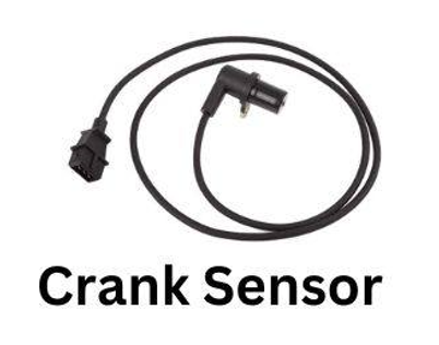
Crankshaft position sensor (CKP). The up and down movements of a vehicle's piston are converted into rotary action by the crankshaft, a rotating shaft forged from steel. A vehicle accelerates due to this rotational force, which is transferred to other parts such as the steering wheel and wheels. The corresponding crank rotates as each piston pushes and pulls on its connecting rod, increasing the crankshaft's total rotation. The IC motor's ability to generate power depends on this conversion of reciprocating motion into rotational motion.
The CKP sensor accurately tracks the rotational position and speed of the crankshaft. This information is essential so that the ECU can accurately control several vital functions.
CKP sensors come in two types: magnetic and Hall effect. When using a magnetic type, a sensing coil and a magnet fixed to the crankshaft interact to provide a voltage signal that changes depending on the position of the magnet. In the Hall effect type, a permanent magnet and semiconductor chip work to detect changes in the magnetic field as the crankshaft rotates, resulting in a voltage output that indicates the position of the sensor. Based on the CKP sensor, the ECU precisely controls fuel injection timing, idle speed control and ignition timing.
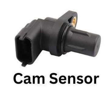
Camshaft position sensor (CMP). The camshaft is a rotating shaft equipped with eccentric lobes (protrusions). These lobes occasionally make contact with the rocker arms when the camshaft rotates. In turn, each rocker arm applies pressure to an appropriate valve (exhaust or intake) on the internal combustion engine. Exhaust gases or air can enter or leave the cylinder by opening the valve.
The camshaft position sensor monitors the position and speed of the camshaft, assisting the ECM in controlling fuel injection and ignition timing. Just as the crankshaft position (CKP) sensor acts as the engine's metronome, the CMP serves as the precise driver of valve dance.
The CMP sensor also comes in two types: magnetic and Hall effect. In the magnetic type, a sensing coil and a magnet on the camshaft interact to provide a voltage signal that varies depending on the location of the magnet. When a camshaft rotates in the Hall effect type, a permanent magnet and a semiconductor chip detect variations in the magnetic field, generating a voltage signal that indicates the position of the camshaft.
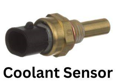
The engine coolant temperature (ECT ) sensor acts as a guardian against overheating by continuously measuring the temperature of the engine coolant flowing through the engine block. Coolant should be at or near 90° C (194° F) for most engines. It is essential to achieve a temperature balance between minimizing heat stress and allowing effective engine performance. The ECU, the brain of the engine, receives this crucial information from the ECT.
There are two types of ECT: thermistor and voltage sensor. A thermistor uses a semiconductor material, and its electrical resistance changes dramatically with temperature. As coolant temperature increases, resistance decreases, and the ECU interprets this change as an increase in temperature. Using a voltage divider circuit, the voltage sensor modifies the output voltage in response to the coolant temperature. This voltage difference is measured by the ECU, which interprets it as a temperature reading.
The engine oil pressure sensor monitors the oil pressure in the engine block or near the oil filter. If the pressure drops below a critical limit, the sensor sends a warning signal to the ECU, vital to prevent engine damage and oil leaks.
There are two types of oil pressure sensors: switches and analog sensors. The switch type works similarly to a pressure switch. It completes a circuit and alerts the ECU when oil pressure drops below a predetermined level. The more advanced analog sensor sends a constant signal to the ECU proportional to oil pressure. After that, the ECU decodes this signal to check the precise pressure level and, if necessary, initiate the necessary action.
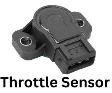
The throttle position sensor (TPS) monitors the position of the throttle valve, allowing the ECU to precisely control the amount of air entering the engine. This, in turn, determines the engine power.
There are two types of throttle position sensors: potentiometers and voltage dividers. The potentiometers have a variable resistor that changes based on the position of the throttle valve. As the valve opens, the wiper on the potentiometer moves, changing the resistance and sending a corresponding voltage signal to the ECU.
Voltage dividers have a fixed resistor and the variable resistance of the butterfly valve to create a voltage divider circuit. The ECU measures the voltage output of this circuit to determine the position of the throttle valve.
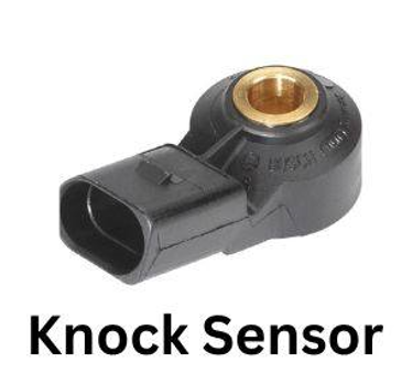
The knock sensor. The combustion process of a vehicle engine must occur smoothly and efficiently. However, in specific circumstances, knocking or premature detonation may occur, causing dangerous vibrations and possible engine damage.
The knock sensor, typically mounted on the engine block, picks up these dangerous vibrations. Engine vibrations are transformed into electrical signals using piezoelectric crystals. When the ECU detects “detonation”, it recognizes that something is wrong and reacts quickly.
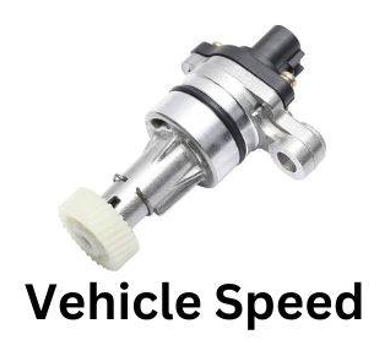
Vehicle speed sensor (VSS) also called transmission speed sensor or output shaft speed sensor, plays a crucial role in the operation of a vehicle by measuring the speed of the wheels or transmission. The speedometer uses sensor data, which displays the vehicle's current speed on the dashboard. It is also used by cruise control to maintain a constant speed set by the driver.
In cars with automatic transmissions, the speed of the vehicle determines the appropriate gear. The traction control system uses this information to prevent wheel slip during acceleration and cornering. Based on data from this sensor, ABS optimizes the vehicle's braking force to prevent the wheels from locking.
There are two types of VSS: wheel speed sensor (WSS) and transmission speed sensor (TSS). The WSS is mounted on each wheel hub and typically uses magnetic or Hall effect technology to measure the speed of the rotating wheel. The TSS is mounted on the transmission output shaft and measures the rotational speed of the shaft, which is directly related to the vehicle speed.
Emission sensors help control pollutants in a vehicle, ensuring it meets environmental regulations. The nitrogen oxide (NOx) sensor measures NOx in the exhaust, helping the engine to reduce these emissions. The Exhaust Gas Temperature (EGT) sensor monitors the temperature of the exhaust gases, ensuring they remain within safe limits.
The steering angle sensor (SAS) tracks the angle and speed of a vehicle's steering wheel movements. This data tells the ECU exactly how much and how quickly the driver moves or turns the steering wheel. SAS relays this information and is used for power steering, traction control, stability control, parking assist, lane departure warning and lane keeping assist. There are two steering angle sensors: potentiometer and magnetic types.
Tire Pressure Monitoring System (TPMS) sensors track a vehicle's tire air pressure, notifying the driver when it deviates from suggested ranges. TMPS sensors come in two varieties: direct and indirect.
Each direct type tire comes with a sensor installed inside the wheel that is powered by a battery. These sensors send real-time pressure and temperature data to the vehicle's onboard computer.
Indirect tire pressure monitoring uses the vehicle's current wheel speed sensors. It analyzes the rotational speed of each wheel and looks for differences in pressure based on changes in diameter. Although less accurate than direct TPMS, it is less expensive and does not require batteries.
The fuel level sensor measures the amount of gasoline remaining in the tank and provides the number from the fuel gauge on the vehicle's dashboard. This sensor sits inside the gas tank and measures the gas level using several technologies.
The conventional method uses a lightweight float connected to a lever that rises and falls in response to the fuel level. When a potentiometer (variable resistor) is positioned differently, the instrument panel receives a voltage signal corresponding to the changed resistance.
However, most cars now have capacitive systems. Inside the tank there are two electrodes. The capacitance between these electrodes is influenced by the fuel level, which changes the voltage signal transmitted to the instrument panel. Ultrasonic sensors are used in some sophisticated systems to measure the distance between the sensor and the fuel surface using ultrasonic waves. The ECU determines the fuel level based on this distance.
Lane Departure Warning (LDW) system sensors continuously monitor and interpret traffic markings. LDW systems use several technologies, including laser, radar and cameras. The most common and efficient type uses a front-mounted camera to detect lane markings. The camera detects the edges of the road and the vehicle by analyzing the images frame by frame. High-resolution cameras work well in well-lit environments, but can have complex lane markings or low visibility challenges.
In some systems, radar sensors complement the camera or operate independently. They release radio waves, which are reflected by the lane markers and then returned to the sensor. By examining the feedback signal, the technology determines the position and distance between the edges of the track. Radar may be less accurate than cameras on clear roads, but it works better in low visibility conditions such as fog or rain.
Laser sensors are sometimes used in high-tech systems for lane detection. They emit laser beams that, like radar, reflect off-track markings to reveal exact positional information. Currently, laser technology is the most expensive and least practical choice.
The voltage sensor measures the voltage of a vehicle's battery and entire electrical system, providing vital information to the ECU and other components to keep the car running smoothly and safely.
Convenience sensors . Various sensors are added to specific vehicle makes and models for a more comfortable driving experience. This may include automatic windshield rain sensors or headlight light sensors that automatically adjust depending on ambient light conditions. There are many others.