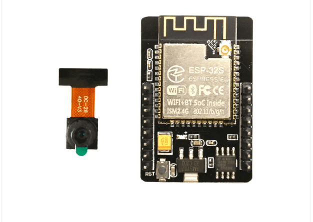
ESP32-CAM is a compact camera module that combines the popular ESP32 Wi-Fi development board with the OV2640 camera sensor. The camera is part of the ESP32 series of Wi-Fi and Bluetooth enabled system-on-chip (SoC) devices developed by Espressif Systems.
ESP32 is a 32-bit dual-core microcontroller with integrated Bluetooth and Wi-Fi capabilities – based on the Espressif IoT Development Framework (ESP-IDF). The OV2640 combo camera module offers a two-megapixel resolution, offering an affordable device for capturing images and videos in an embedded application or Internet of Things (IoT) device.
 ESP32-CAM has a MicroSD card slot, which can be used for image and video storage. It also provides enough general-purpose input-output (GPIO) pins on the module to directly interface with sensors and other peripherals.
The module can be easily programmed using the Arduino IDE with the appropriate ESP32 board support package or the ESP-IDF for more advanced development. Programming is supported by a broad, active, open-source community support, with numerous online libraries and examples.
However, despite its advantages, ESP32-CAM also has some disadvantages. In this article, we will review some common problems with working with this camera module and offer potential solutions.
Why choose ESP32-CAM?
The ESP32 camera offers several advantages for adding image or video streaming functionality to embedded applications. The camera module is compact, with built-in Wi-Fi and Bluetooth. It easily integrates with any IoT network and can operate in sleep mode to extend battery life in portable projects.
This low-cost module has a MicroSD card slot with internal connections to its GPIO for local storage of images and videos. It offers enough GPIO to directly interface additional sensors or peripherals with the module. It can also be programmed from the Arduino IDE and has a large open source community, making it ideal for beginner or intermediate applications.
Module limitations
ESP32-CAM is attractive because it is easy to use and affordable. However, it is not ideal for computationally intensive tasks such as running complex machine learning algorithms. The available RAM on the module is insufficient for high-resolution image processing tasks. The camera resolution of the integrated OV2640 sensor is just two megapixels.
A big disadvantage of the ESP32-CAM is that it doesn't have a USB port on most breakout boards, so you need to use an external FTDI programmer or an Arduino board to flash code on the module. The module also does not have built-in security measures when connecting to a network, which must be added to the embedded firmware if necessary.
Additionally, ESP32-CAM breakout boards get hot, especially with video streaming, potentially requiring heatsinks. Although there is good community support for ESP32-CAM, the documentation is not ideal. It is a steep learning curve to transition to ESP-IDF to build advanced projects using ESP32-CAM.
Forms
The ESP32-CAM is a versatile module thanks to its integrated Bluetooth, Wi-Fi and MicroSD card capabilities. It is useful in IoT projects such as home automation, environmental monitoring, security and surveillance. It is also useful for machine learning projects such as object detection, facial recognition, and other simple to intermediate image-based tasks. The module can even be used for wildlife monitoring and time-lapse photography.
Common problems with ESP32-CAM
- Power supply issues
- Failed to connect to ESP32
- Camera initialization failed
- Power outage detector
- Memory Problems
- COMX board not available
- Psram error
- Wi-Fi Connectivity
- No IP address on Arduino IDE serial monitor
- Unable to open web server
- Image quality
- Image latency
- Overheating
- Security
- esp_camera_fb_get : Failed to get frame in time!
Let's discuss these problems and their possible solutions.
Power supply problems
The ESP32–CAM may not turn on or may reboot frequently. This is usually due to an inadequate or unstable power supply. Ensure that a stable power supply with a current capacity of at least 500 mA is powering the module. Also, use a quality USB cable and power supply, avoiding longer cables if possible.
The camera's LED flash typically consumes additional power and powering it from the ESP32-CAM may cause voltage drops. Ideally, use an external battery, which is also good for portability. If powering the module through an FTDI programmer, use a 5V source instead of 3V3.
Connection Failed: Timed out while waiting for packet header
This error occurs when loading a sketch into the ESP32-CAM and indicates that the module is not in flash mode or is not correctly connected to the FTDI programmer.
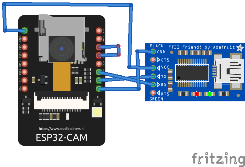
The circuit diagram to correctly load a sketch into the ESP32-CAM via the FTDI programmer is as follows.
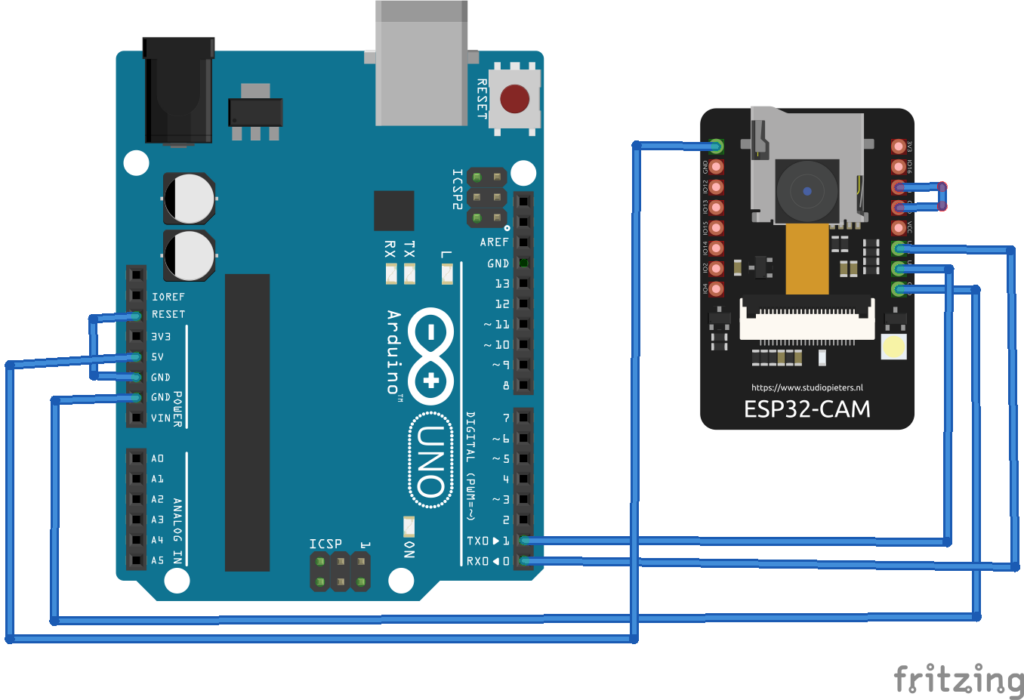
The circuit diagram to send the sketch to ESP32-CAM through Arduino is as follows.
If using an FTDI programmer, the programmer may have a jumper to select between 5 and 3.3 V. If so, make sure the jumper is positioned so that 5 V is selected and the ESP32's GPIO0 -CAM is correctly connected to ground. Otherwise, the module will not enter flashing mode.
Additionally, any FTDI programmer based on the CH340 model will not work with the ESP32 camera. Choose an FTDI programmer compatible with ESP32-CAM or flash code using Arduino. If using Arduino, make sure its reset pin is also connected to its ground.
After making the proper circuit connections between the ESP32-CAM and the FTDI/Arduino programmer, ensure that the proper settings are selected. For example, select 'ESP32 Wrover Module' or 'AI-Thinker ESP32-CAM' according to your ESP32 camera model in Tools->Board. Also, choose the correct port for the Arduino or FTDI programmer and make sure it is connected under Tools->Port. When the upload button is clicked and 'Connecting…' is displayed in the debug window, press the ESP32-CAM reset button. The sketch should start uploading to the camera module.
Camera initialization failed
This issue indicates that the code pin assignment is incorrect or that the OVX camera is not correctly linked to the ESP32 board. The problem can sometimes be resolved by repeatedly restarting the board or unplugging and plugging in the FTDI programmer.
However, there is more than one potential reason for this error message. The camera has a tiny connector, so ensure it is connected securely. Additionally, verify that the correct camera model is selected in the code and that the ESP32-CAM pin definition is correct within the sketch. In your projects, choose the appropriate camera module. Each camera module must be “commented”, but leave the correct one “uncommented”.
It is important to note that the wiring between the ESP32 and the OV camera on many boards is considered “dummy boards”, so there is a chance that choosing the correct camera module will be insufficient. You may need to compare your card's pinout to each GPIO statement.
It is also possible that the FTDI programmer is faulty or your computer's USB port is not providing enough power to the camera module. Consider using another FTDI programmer or USB port.
This error also occurs when the camera sensor is not properly connected to the module. The camera tape may be broken, or the OV2640 sensor may be defective.
Power outage detector
After sending the sketch to the ESP32-CAM, disconnect GPIO0 from ground on the camera module. After uploading the sketch, open the Arduino Serial Monitor and press the reset button on the module.
If you receive the error message “The power outage detector has been triggered” repeatedly on the serial console, the typical reason is because:
- The USB cable is too long or of poor quality
- The computer's USB port is not working properly
- The USB port is not providing enough power
- The board is defective
Try using a different USB cable or different USB port. For example, consider using a USB hub with an external power supply. Or try using a 5V source instead of 3.3V for the ESP32-CAM. If none of these solutions work, disable Brownout detection by adding the following lines of code to your sketch.
#include “soc/soc.h”
#include “soc/rtc_cntl_reg.h”
empty configuration {
WRITE_PERI_REG(RTC_CNTL_BROWN_OUT_REG, 0);
}
Memory Problems
The ESP32-CAM has limited RAM, so memory-related issues may occur when working with large images or complex programs. Efficient memory management is crucial to avoid crashes.
You may encounter a 'Sketch too large' error while submitting the sketch. Make sure you select the correct partition scheme. Navigate to Tools->Partition Scheme and select 'Huge APP (3MB without OTA).'
COMX plate not available
If the “Board at COMX is not available” error occurs, you probably did not select the correct Arduino COM port. Navigate to Tools->Port and the COM port your ESP32 is connected to. A problem with the USB cable or USB port on your computer can also generate this error.
PSRAM error: GPIO ISR service is not installed
This error will occur if your ESP32-CAM board does not have PSRAM. Image-based tasks like facial recognition and object detection are impossible on these cards.
The ideal is to choose an ESP32-CAM model that has PSRAM. But if you have a board without PSRAM, an alternative solution is to lower the resolution of the image in the sketch.
Add the following lines of code to the sketch.
if(psramFound){
config.frame_size=FRAMESIZE_UXGA;
config.jpeg_quality = 10;
config.fb_count = 2;
} other {
config.frame_size=FRAMESIZE_SVGA;
config.jpeg_qualidade = 12;
config.fb_count = 1;
}
Wi-Fi Connectivity
Wi-Fi network issues can occur due to incorrect credentials, signal strength, or interference. Double-check your Wi-Fi signal strength and update the firmware if necessary.
Also, try different antenna positions for better reception. The ESP32-CAM can be configured to use an external or built-in antenna, which can be used if the Wi-Fi signal is weak.
If not, check that the 0K jumper resistor near the antenna connector is positioned correctly. Three small white squares are arranged as “<”, with the middle position typically being the most popular. The resistor must be in the upper position to use the PCB antenna and in the lower position to use the antenna connector. To activate the integrated antenna, unsolder the resistor that is connected to it and solder the two connections.
No IP address in Arduino IDE Serial Monitor
If there is a reliable Wi-Fi signal, but dots (like '………') still occur on the serial console, then the ESP32-CAM is not properly connected to the Wi-Fi network. There could be several reasons for this.
Double-check the following, ensuring:
- You entered the correct Wi-Fi network credentials in the sketch.
- The transmission rate of ESP32-CAM is 115,200 bps.
- The TX and RX pins of the ESP32-CAM are securely connected to the TX and RX pins of the Arduino or FTDI programmer.
Connecting the TX of the ESP32-CAM with the Arduino or the RX of the FTDI programmer and/or the RX of the ESP32-CAM with the Arduino or the ESP32-CAM of the FTDI programmer is a common mistake. “TX” must be connected to “TX” and “RX” must be connected to “RX” for proper serial communication. Sometimes repeatedly pressing the reset button on the camera module also solves the problem.
Unable to open web server
When the ESP32-CAM reports the IP address in the Arduino Serial Monitor IDE, but a blank screen appears when opening the web server in a browser, you may be accessing the web server through multiple tabs.
The ESP32-CAM can only handle HTTP requests from a single client, so try accessing the web server from a single browser tab.
Poor image quality
If you are connected to a web server but receive blurry or distorted images, try adjusting your camera settings – including resolution, frame rate, and white balance. Ensure proper focus by adjusting the lens. Also, try cleaning your camera lens to get clear images.
Image latency
There may be latency when viewing images or video streams on the web server with some modules. This can be resolved by using an independent 5V power supply for the camera module. In some cases, it is useful to use an external antenna.
If there are still latency issues, try reducing the frame size by adding the following line of code to the sketch.
config.frame_size = SVGA_FRAME_SIZE
Or alternatively, try this:
config.frame_size = VGA_FRAME_SIZE
Overheating
The ESP32-CAM may overheat, especially during video streaming. Try reducing the video resolution and frame rate. Add a heatsink to dissipate heat, especially for demanding tasks, and ensure adequate ventilation in the project case.
Security
There are potential security vulnerabilities with the ESP32-CAM when connected to the Internet. These security flaws can be avoided by using strong passwords and encryption. You can also implement authentication and authorization mechanisms if necessary. Always keep firmware updated for security patches.
esp_camera_fb_get : Failed to get frame in time!
This error typically occurs with M5 models and those without PSRAM. For model M5, the issue can be resolved by adding pin assignments in the sketch.
Consider adding this line of code to the main outline.
#define CAMERA_MODEL_M5STACK_WITHOUT_PSRAM
Then, in the camera_pins.h tab, add the following lines of code:
#elif defined(CAMERA_MODEL_M5STACK_NO_PSRAM)
#define PWDN_GPIO_NUM -1
#define RESET_GPIO_NUM 15
#define XCLK_GPIO_NUM 27
#define SIOD_GPIO_NUM 25
#define SIOC_GPIO_NUM 23
#define Y9_GPIO_NUM 19
#define Y8_GPIO_NUM 36
#define Y7_GPIO_NUM 18
#define Y6_GPIO_NUM 39
#define Y5_GPIO_NUM 5
#define Y4_GPIO_NUM 34
#define Y3_GPIO_NUM 35
#define Y2_GPIO_NUM 17
#define VSYNC_GPIO_NUM 22
#define HREF_GPIO_NUM 26
#define PCLK_GPIO_NUM 21
This should resolve the issue.
Conclusion
For simple image processing tasks in IoT devices and embedded applications, the ESP32-CAM is a good choice. It is efficient, affordable and easy to integrate. However, some problems may occur with this module. Fortunately, most of them can be resolved by following simple suggestions.