In this series of tutorials, we learned about potentiometer interface to get analog input, RGB LED interface generating PWM output, DC motor speed control using PWM output and some other things.
This tutorial explains the serial communication of the ATtiny85 with the HC05 Bluetooth module. ATtiny85 does not have integrated UART or USART with Rx and Tx pins, but supports configurable USI (Universal Serial Interface). Arduino programming allows us to use digital IO pins as Tx and Rx pins using the SoftwareSerial library. So using this library we will make pin 7 (PB2) and pin 2 (PB3) of ATtiny85 work as Rx and Tx pins. The HC05 Bluetooth module communicates with ATtiny85 using these Tx and Rx pins.
The most interesting part is yet to come. The HC05 module receives Bluetooth commands from any smartphone through the Android application – which sends commands from the phone's integrated Bluetooth. So the smartphone sends a command to the ATtiny85 through the HC05 module to control any device. Sounds interesting? Let's see how this is done.
If you haven't been following the series from the beginning, you should go through the following two tutorials that explain and demonstrate how to work with ATtiny85 and step-by-step guide to building the hello world (LED blinking) app.
How to work with ATtiny85
LED blinking using ATtiny85
Circuit Diagram
 Circuit Connections
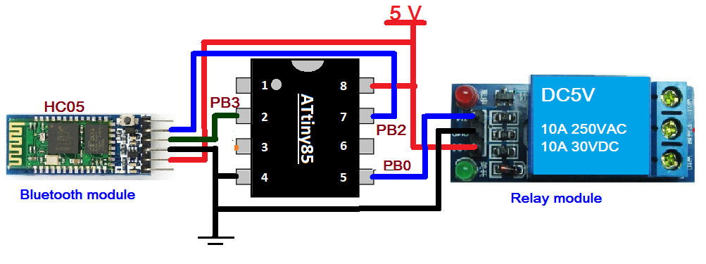
The circuit is built using just three components: HC05 module, relay module and ATtiny85. The HC05 (Bluetooth module) has four interface pins (1) Vcc (2) GND (3) Tx and (4) Rx. The Tx pin is connected to PB2 (pin 7) and the Rx pin is connected to PB3 (pin 2). Vcc pin is connected with 5V and GND pin is connected with pin four connected to ground. The relay module has three interface pins (1) Vcc, (2) GND and (3) IN. The Vcc pin is connected with 5V because the relay is 5V. The GND pin is connected to pin 4 of the ATtiny85. PB0 pin is connected to IN pin to turn on/off the relay. A 5V supply is provided in the circuit.
Note: You can connect any AC (or DC) device with a relay to its contact terminals so that when the relay is turned on/off, the device will be turned on/off
Circuit operation
- When a 5V supply is sent to the circuit, the relay is OFF (so the device will also be OFF). The HC05 module will begin blinking to indicate that it is searching for another Bluetooth device to pair (connect) with.
- The person who wants to control the device will first open the Android app having Bluetooth data sending feature on their smartphone (You can get many such apps from Google Play Store. Search “Bluetooth Control for Arduino”). This app will search and pair with the HC05 module (to pair 1st time, you need to enter the Bluetooth password for the HC05 module, which by default is 1234). When the smartphone is connected to the HC05 module, its blinking rate will be slow
- Now type and send '1' from the app. The phone's Bluetooth will send this '1' to the HC05 module
- The HC05 module will receive this '1' and deliver it to the ATtiny85 via serial communication
- When ATtiny85 receives command 1, it turns on the relay sending high to pin PB0. The device connected to the relay is also ON
- Now to turn off the device (relay), the person has to send the command '0' from the smartphone
- Thus, the device is turned ON/OFF by sending commands via the smartphone
Program
The program is written in Arduino IDE software using the C programming language. It is compiled and a HEX file is created that is downloaded to the ATtiny85's internal FLASH
Program logic
Initially, the program sends a message to the user's smartphone informing that the Bluetooth phone is connected to the HC05 and sends the 1/0 command to turn the device on/off.
It then waits for any available data on the serial port. If command '1' or '0' is received, it will turn on/off the relay by sending HIGH/LOW to the input pin of the relay module. Additionally, it sends a message to the user's smartphone informing that the device is ON/OFF.
In the next tutorial, we will learn how to build a wireless sensor data logger.