In previous tutorials in this series, we saw how to generate different chase effects by flashing LEDs. So we were simply turning the LED on and off.
In this tutorial we will vary the brightness (intensity) of the LED. We will use the ATtiny85's PWM output to do this. So let's see how to do this.
If you are not following this tutorial series from the beginning, you should go through the following two tutorials that explain and demonstrate how to work with ATtiny85 and step-by-step guide to building a hello world (blinking LED) app.
How to work with ATtiny85
LED blinking using ATtiny85
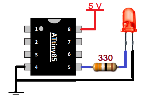
Circuit Diagram

Circuit Connections
The circuit diagram is very simple. Only one LED is connected to PB0 pin (pin 5), which is also the PWM output pin. A 330 resistor is used to limit the current. A 5V supply is connected to a Vcc pin (8).
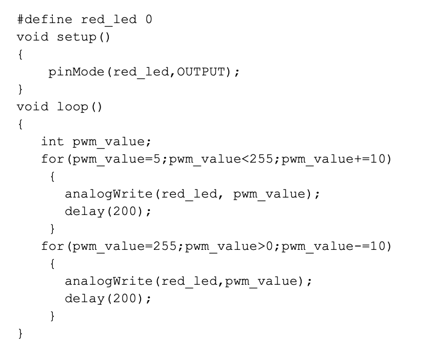
Program
The program is written in Arduino IDE software using the C programming language. It is compiled and a HEX file is created that is downloaded to the ATtiny85's internal FLASH.
Program logic
The program logic is straightforward. First, the PWM output is gradually increased from 5 to 255 (maximum width) in increments of 10. This PWM is given to the LED, so its intensity will gradually increase. The LED intensity goes from 0 (min) to full (max) in 5 seconds. Then the PWM output gradually decreases from 255 to 0 in increments of 10. Thus, the LED intensity will gradually decrease from maximum to minimum again in 5 seconds. Once again the PWM value begins to increase and this cycle repeats itself continuously. Therefore, the LED intensity increases and decreases continuously.
In the next tutorial we will learn how to vary the LED brightness using a potentiometer.