In the previous tutorial in this series, we saw how to work with ATtiny85, how to program it, and we also built our first – hello world app – which is an LED blinking app using ATtiny85.
So let's extend it to the next step – meaning one step forward. We will connect 5 LEDs with 5 port pins of ATtiny85 and generate different chasing effects. Five LEDs of different colors are connected to the ATtiny85, and it will flash them in a different pattern at a different rate, creating eye-catching multi-color chasing effects. So let's see how to do this.
If you are not following this tutorial series from the beginning, you will be prompted to follow the following two tutorials that explain and demonstrate how to work with ATtiny85 and a step-by-step guide to building a Hello World (Blinking LED) app.
How to work with ATtiny85
LED blinking using ATtiny85
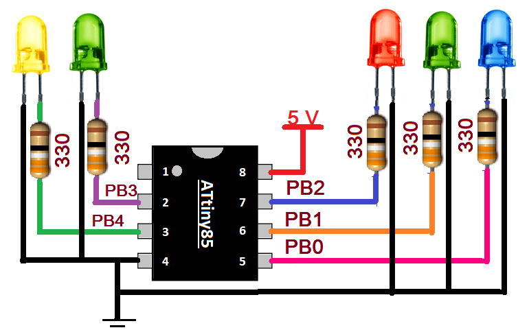
Circuit Diagram

Circuit Connections
As you can see, 5 LEDs of different colors are connected to 5 port pins of the ATtiny85. The anodes of the LEDs are connected to the PORTB pins PB0 (pin 5), PB1 (pin 6), PB2 (pin 7), PB3 (pin 2), PB4 (pin 3) through 330Ω current limiting resistors. All the cathodes of the LED are connected to pin 4, which is the Gnd pin. A 5V supply is connected to a Vcc pin (8)
Program
The program is written in Arduino IDE software using the C programming language. It is compiled and a HEX file is created that is downloaded to the ATtiny85's internal FLASH.
Program logic
The program logic is straightforward. The program generates 3 different chase effects. Each effect lasts 50-60 seconds (approximately 1 min) and repeats one after the other continuously as effect1 – effect2 – effect3 – effect1 – effect2 –…..
The first effect is the simplest. Each LED flashes in sequence from led1 to led 5.
In the second effect, one by one, all LEDs are lit from led1 to led5, and then all are turned off in the reverse sequence from led5 to led1.
In the third effect, the alternating LED is ON and OFF means led1-led3-led5 are ON and led2-led4 are OFF, and after the delay, led1-led3-led5 are OFF and led2-led4 are ON.
In the next tutorial we will learn how to vary the LED brightness.