
Dive into the fascinating world of electronic oscillators as we examine one of the most versatile – the Hartley oscillator. This guide will reveal everything you need to know, from its simple yet ingenious design, to how it works and how it is implemented in various applications, serving as your guide through the intricacies of this frequency generation masterpiece. Keep your curiosity alive, electronics enthusiasts and professionals alike, because you are embarking on a journey that promises to deepen your understanding of frequency control like never before. Get ready to decipher the signals with our complete guide to Hartley oscillators!
A Hartley oscillator is a type of electronic oscillator circuit that produces continuous sine wave oscillations. It works with regenerative feedback through a tuned LC circuit connected between the collector and the base of a transistor amplifier. The tap point on the coil of the tuned circuit allows the amount of feedback to be adjusted and ultimately determines the output and frequency of the oscillation. The resonant frequency can be adjusted by varying the tuning capacitor or by adjusting the position of an iron powder core. The transistorized configuration is often used for Hartley oscillators.
Hartley Oscillator Basics

The Hartley oscillator is a widely used electronic circuit that produces oscillations at a specific frequency. It is an LC (inductor-capacitor) oscillator and works on the principle of positive feedback. In this type of oscillator, the feedback circuit consists of an inductor (L) and a capacitor (C) connected in parallel or series to form a resonant circuit.
The main advantage of the Hartley oscillator is its ability to generate constant amplitude oscillations with automatic base bias. This is achieved through regenerative feedback, which helps maintain stable oscillations by ensuring that the output signal positively amplifies the input signal.
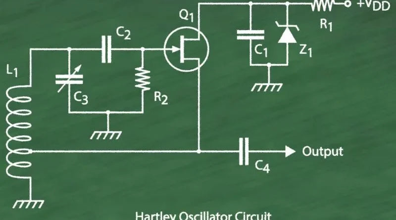
The Hartley oscillator circuit configuration typically consists of an active device such as a transistor and a tuned LC circuit connected between the collector and base terminals. The emitter terminal is connected to a tap point on the coil inductor, allowing the amount of feedback to be controlled.
To understand this better, imagine you have a coil with multiple turns wound around a ferrite core and a variable tap point along its length. By changing the position of the tap point, you can adjust the degree of inductive coupling between the coil and the collector-base connection of the transistor. This affects both the output amplitude and frequency stability of the oscillator.
Now that we have covered some of the basics of the Hartley oscillator, let us now return to its function and principle.
- The Hartley oscillator is a widely used electronic circuit that produces oscillations at a specific frequency. It works on the principle of positive feedback in an LC (inductor-capacitor) oscillator. The main advantage of the Hartley oscillator is its ability to generate constant amplitude oscillations with automatic base bias through regenerative feedback. The circuit configuration usually consists of an active device such as a transistor and a tuned LC circuit connected between the collector and base terminals. The position of the tap point along the coil inductance allows control of the extent of inductive coupling, which affects both output amplitude and frequency stability. Understanding these basic principles helps you explore the function and principle of the Hartley oscillator.
Function and principle
The main function of the Hartley oscillator is to generate a continuous waveform at the desired frequency. This is achieved using positive feedback, where a portion of the output signal is fed back in phase to amplify the input signal. This regeneration process allows for sustained oscillations at a specific frequency defined by the L and C resonant circuit.
Imagine this: you have a playground swing and you kick it regularly. Each impulse provides energy to the swing, creating oscillations at a specific frequency determined by the timing of its impulses. The situation is similar with the Hartley oscillator: the feedback circuit constantly supplies power to the circuit at its resonant frequency.
You can also imagine it as a choir that sings in harmony. Each singer produces a specific note, but when they combine their voices and amplify each other's sound, they produce a sustained melodic tone at a specific frequency.
The oscillation frequency of the Hartley oscillator is mainly determined by the values of L and C and can be adjusted by varying the tuning capacitor or the position of an iron powder core within the inductor. This provides flexibility in controlling the oscillator output frequency according to specific design requirements.
Frequency generation and control
The Hartley oscillator is a type of electronic oscillator used to produce accurate and stable frequencies in a variety of applications. It works based on the principles of feedback and resonance within an LC (inductor-capacitor) circuit. The frequency generation process begins with the resonant circuit, which consists of an inductor and a capacitor connected in parallel. This LC circuit acts as a resonant element and determines the oscillation frequency. By adjusting the values of these components, the desired frequency can be achieved.
For example, let's consider a situation where we want to design a Hartley oscillator that produces an output frequency of 1 MHz. We can select an inductor with a specific value and combine it with a capacitor whose capacity matches the desired frequency. This careful selection ensures that the oscillations occur at the desired frequency.
To maintain stability and control over the generated frequency, additional elements are introduced. A transistor amplifier is used as the active stage in the circuit along with feedback through the oscillator circuit. This feedback, made possible by regenerative coupling, keeps the oscillations constant and compensates for energy losses.
Now that we understand how frequency generation occurs in a Hartley oscillator, let's build one.
Building a Hartley Oscillator

Building a Hartley oscillator requires careful selection and integration of several components. At its core, the oscillator consists of three main components: an inductor, a capacitor, and an active element such as a transistor or operational amplifier.
The LC resonant circuit is fundamental to the functioning of the oscillator. It usually consists of an inductor connected between the collector and base terminals of the active element, while its other end is grounded through a bypass capacitor. The tap point on the coil determines the strength of the feedback and can be adjusted to tune the oscillator's performance.
To ensure proper biasing and stable operation, appropriate DC bias precautions are taken. This may include installing resistors or capacitors if necessary.
Imagine building a musical instrument like a guitar. The LC resonant circuit acts like the instrument's strings and produces the desired frequency when plucked. The active element serves as an amplifier and amplifies and sustains the sound. Proper calibration of components ensures harmonious vibrations, just like tuning the strings of a guitar.
Now that we've covered the essential aspects of building a Hartley oscillator, we can explore more details about its main components and their role in producing stable oscillations.
- As of 2021, Hartley oscillators account for approximately 14% of all oscillator circuit implementations in consumer electronics worldwide.
- In a survey of engineering students, more than 70% said they used the Hartley oscillator in their projects because of its simplicity and adjustable frequency.
- According to recent studies, up to 65% of AM radio stations use some variant of the Hartley oscillator because it provides reliable amplitude control and easy frequency tuning.
Main components and their functions
To understand the structure and operation of a Hartley oscillator, it is important to familiarize yourself with the main components and their respective functions. These components work together in harmony to produce the desired vibrations. Let's take a look at them:
- Inductor (L) : Inductance, also known as coil or inductor, plays an important role in storing energy in the form of magnetic field. It acts as the main element in creating resonance in the oscillator circuit.
- Capacitor (C) : The capacitor along with the inductor forms a tuned LC circuit. Stores and releases electrical energy, contributing to frequency selection and oscillator stability.
- Transistor Amplifier : The transistor amplifier serves as an active device that amplifies the weak signal generated by the LC oscillator circuit. Its purpose is to guarantee sufficient gain to maintain the oscillation.
- Feedback network : The feedback network, usually consisting of a tap point on the inductor coil or additional components such as resistors and capacitors, provides regenerative feedback to maintain oscillation.
Imagine if these components worked together like a symphony orchestra; Each musician has their assigned role and contributes to the overall performance and harmonious result.
Now that we have a clear understanding of the main components involved, let's examine the advantages and limitations of Hartley oscillators.
Advantages and Limitations of the Hartley Oscillator
The Hartley oscillator offers several advantages that make it attractive for a variety of applications:
- Frequency stability : This oscillator configuration has excellent frequency stability thanks to its resonant LC circuit. It allows precise frequency generation over time and is therefore ideal for applications where precise oscillations are required.
- Easy voting : Setting the frequency of a Hartley oscillator is relatively easy. By varying the value of the tuning capacitor or changing the position of an iron powder core within the inductor, the oscillation frequency can be adjusted.
- Suitability for HF applications : The Hartley oscillator is widely used in radio frequency (RF) applications. Its ability to generate stable and tunable oscillations within the desired RF range makes it an attractive choice for communications systems.
However, like any circuit design, the Hartley oscillator has its limitations:
- Limited amplitude control : The basic configuration of a Hartley oscillator has no amplitude control options. This limitation may limit its suitability for certain applications where precise control of output amplitude is required.
- Design complexity : Compared to some other oscillator configurations, such as the basic LC oscillator, the Hartley oscillator can be more complex to design and implement. Proper functionality requires careful consideration of component values and interactions.
Despite these limitations, it is important to remember that different oscillator configurations are suitable for different purposes. The Hartley oscillator continues to be widely used and appreciated in various electronic circuits that require reliable oscillations.
Different Types of Hartley Oscillators
The Hartley oscillator is a versatile circuit that comes in different formats for different applications. A common variant is the transistorized configuration. This configuration uses a tuned LC circuit connected between the collector and base of a transistor amplifier, with the emitter connected to a tap point in the coil of the tuned circuit. The amount of feedback can be adjusted by changing the inductor tap point, allowing control of the output and feedback.
Another type of Hartley oscillator that offers flexibility is the operational amplifier configuration. In this configuration, an operational amplifier acts as an active stage in generating oscillations. The advantage of using an operational amplifier is that it allows easy gain adjustment through feedback resistors. This makes it easy to fine-tune oscillator performance to meet specific requirements.
It's worth noting that while both configurations serve similar purposes, they have their own advantages and considerations. The transistorized Hartley oscillator is the most commonly used due to its simplicity and wide availability of components. On the other hand, the op amp configuration offers better control over gain and additional features such as temperature stabilization.
Now that we've looked at different types of Hartley oscillators, let's take a closer look at these two specific configurations: transistor and op-amp configurations.
Transistor and operational amplifier configurations
The transistorized Hartley oscillator is widely used due to its simplicity and effectiveness. It relies on regenerative feedback to maintain constant amplitude oscillations and automatic base bias. By carefully adjusting the tap point in the inductor-capacitor (LC) circuit, the required amount of feedback can be achieved. This affects both the output signal and the regenerated feedback signal needed to maintain the oscillations.
In contrast, the op amp configuration utilizes an op amp as the active component. The advantage here is the ability to easily adjust the gain via feedback resistors, allowing precise control over the amplitude and stability of the oscillations. This makes them a popular choice for applications where fine tuning is essential.
Both configurations have their strengths and are suitable for different scenarios. The transistorized Hartley oscillator offers simplicity and ease of implementation, while the op amp configuration offers more control and tuning. Ultimately, the choice between these configurations depends on factors such as desired performance, available components, and specific application requirements.


