Recent versions of SIMULINK have a support package for Arduino (UNO, Mega2560, etc.), BeagleBone, etc. This made it easier to mock up and send designs directly to the board.
In this project, we will use the SIMULINK Tool to blink an LED connected to our Arduino UNO.
It is a block diagram based tool in which there is no need to write code in C or anything like that, instead the block diagram model is directly converted and loaded on the board by MATLAB tools. To start, we will generate an LED Blink code and run it on the Arduino-UNO.
But before you start, you need to check some prerequisites. Your computer must have Matlab-R2013 or higher (this tutorial is on MATLAB-R2014a). If you have the student version of MATLAB -2013 or 2014, it will do.
Now we need to install the Arduino Support Package from the official MathWorks website,
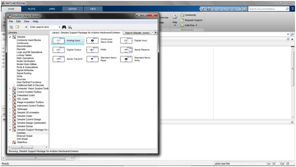
After completing the steps above, let's start creating our system design:When you open MATLAB, a screen appears with several embedded windows, viz. Command window, etc. Select the SIMULINK library from the main window menu bar.
You will see a pop-up screen as follows:
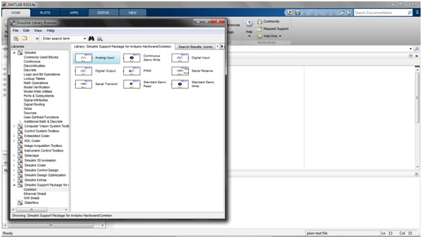
Go to 'Simulink Support Package for Arduino' and you will see a screen like above.
Cont..
Select Digital Output from the list to control the LEAD . Right click and select 'Add to new template'.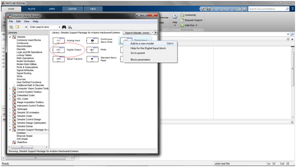
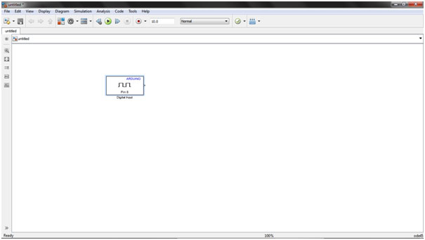
After that, you will see a Simulink model window as shown below:
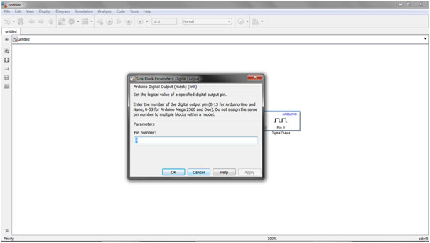
After that, we need to generate a pulse , which will turn our LED on and off. To achieve this, click on Simulink Library again. Go to 'Sources' and select Pulse Generator from the list and add it to the template by right-clicking on it.
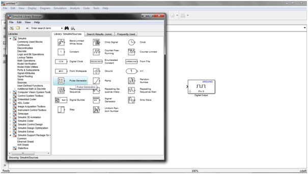
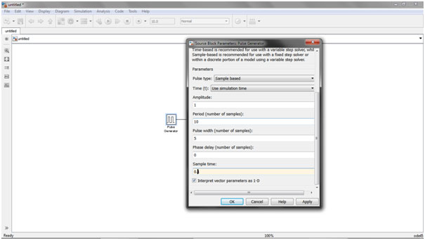
Connect the two blocks together. Now double click on 'Pulse Generator' to edit its properties. You can set the delay, sampling time, etc. of your choice. As an example, you can define the ones shown below:
After completing the above steps, we will define the 'Target Hardware' and set its properties. Go to ' Tools ' in the menu bar and select ' Run on target hardware ', a pop-up window will appear as shown below:
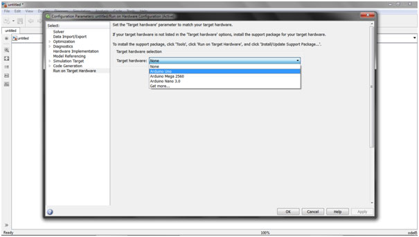
Select the target hardware (say Arduino UNO) and choose the COM port. You can select it manually if it doesn't work automatically.
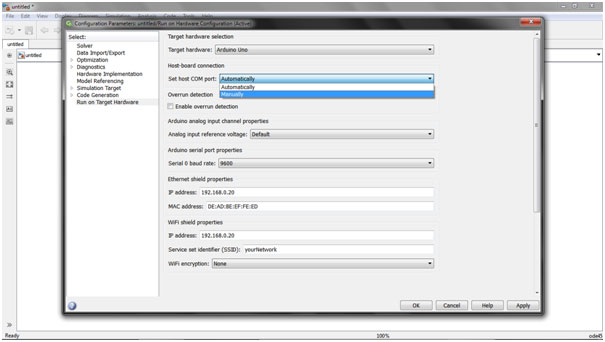
Select 'Apply' and click OK. Congratulations…!!!
We are just one step away. From the menu bar, select the ' Deploy to hardware ' option.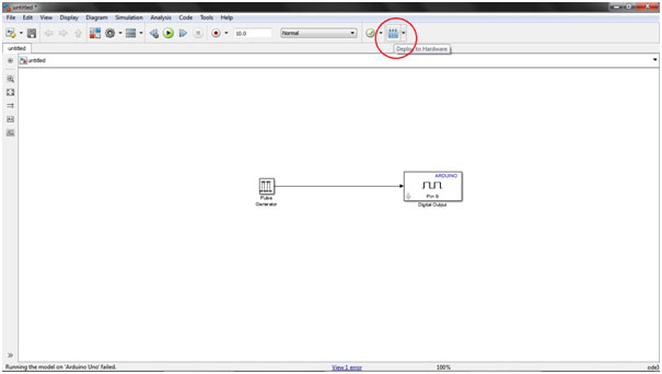
If it shows errors, recheck the COM port from Device Manager->Ports.
As an extension of the above system, you can add input devices, add logic to your project or design your first line follower robot in Simulink..!!!
