Providing a suitable delay like 1 second OR 1 minute is only possible using internal timers of 8051 microcontroller (89c51,89c52). The 8051 series microcontrollers have two built-in 16-bit timers, Timer 0 and Timer 1. Some also have an extra timer, Timer 3. You can use them to generate delays, baud rate to UART
for serial communication OR drive a source event function to execute an interrupt whenever a specific condition is met. I highly recommend you to do a simple tutorial on internal timer registers of 8051 microcontrollers(89c51,89c52) and registers associated with them.
-
The registers associated with the 89c51 microcontroller timers.
If you don't know the internal registers dedicated to timers, you won't be able to understand the tutorial and code below. Generating delays of specific time is not easy using internal timers of 8051 microcontrollers. It requires extensive knowledge to generate delays properly.
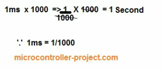
The project/tutorial is simple, just blinking an LED every 1 minute. I calculated the delay as 2 ms and loaded the calculated values into the TH and TL registers. To calculate the values, access the tutorial link provided above. Now, if I run a 2 ms delay for 500 times, it will generate a 1 second delay. Running this 1 second delay for 60 times gives me a 1 minute delay.
Delay generation using 8051 (89c51) microcontroller timers
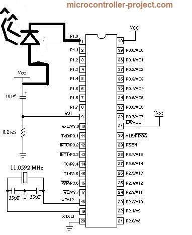
1 Second Delay Circuit Diagram of 8051 Microcontroller
The circuit diagram is quite simple. The LED is connected to pin #0 of port 1. Setting this pin high and low will make the LED blink. The main function is easy to understand. The delay function is generating a 1 minute delay for us. At the top is the for loop, which is running 60 times. To generate a 1 minute delay, the Loop is running 60 times generating 60 seconds. So the while loop is running 500 times to generate a 1 second delay.
The above tutorial is very important to understand the delay function. I calculated the TH and TL register values for 2ms delay and ran them for 1ms (500 times). The code is generating exactly 1ms of delay.
Port 1 Pn#0 is connected to the – (negative) led leg. Apply 5 volts to the + (positive) leg of the LED. Connect the oscillator (11.0592 MHz) with PINs #18 and 19 (XTAL0, XTAL1) of the 89c51 microcontroller. Apply 5 volts to pins #40 and 31 of 8051 (89c51). Grounding pin #20.
LED with microcontroller 8051(89c51)
Please do the tutorial if you are not familiar with the internal timer registers of 8051(89c51,89c52) microcontroller. The tutorial will help you understand the code below.
- 8051 TIMER RECORDS AND THEIR WORKING
I made a digital clock with an 89c51 microcontroller using the time delay technique above. You can see the post. Every design code and circuit diagram is free.
- Digital Clock with Microcontroller 89c51.
- Calculator with 89c51 microcontroller.
- HOW TO MAKE A SECOND DELAY
Download project files, code (c and hex) compiled in c using keil U-vision4. If you have any queries regarding the post, please write your queries below.
One minute delay generation with 89c51 microcontroller