Dimming or controlling the brightness of LED using arduino uno and variable potentiometer/resistor is not a very difficult task. The Arduino predefined libraries made it very easy to dim the LED with the Arduino Uno. It is important to understand what is behind the predefined commands/instructions of the Arduino code at the software and hardware level. Students typically start with the pre-written Arduino code examples available in the Arduino ide and never try to understand what is actually going on behind the visible spectrum. Therefore, when they move to a higher level of Arduino programming, they face hurdles in properly designing the circuit and implementing the code logic for the specific hardware. In this tutorial I will explain how to control the brightness of an LED using Arduino and a potentiometer/variable resistor.
You can find the Arduino analog fade and Arduino serial input/output example in the Arduino IDE. The examples are more or less the same as what I will discuss in this tutorial. I will go deeper and try to highlight each piece of information as broadly and easily as possible.
The potentiometer is used in circuits where we need a variable resistance to control current and voltage. Have you ever noticed that on the speaker you have in your home, you move its knob clockwise and counterclockwise to adjust the volume. In fact, behind the button there is a potentiometer, that is, you vary the resistance to set the volume. Likewise, in many other household appliances, the potentiometer is used for the same purpose (old TVs, old radios, etc.).
What happens on the potentiometer side?
When we turn the potentiometer knob we are actually increasing or decreasing the resistance. Remember that the potentiometer is a variable resistor and nothing more. The resistance range of the potentiometer is written on the potentiometer or you can manually check the specific potentiometer's datasheet to check its resistance.
Now remember Ohm's law that whenever resistance in a circuit increases, current decreases. Furthermore, current is directly proportional to voltage. Thus, with increasing voltage, current increases and with decreasing voltage, current decreases.
If we consider the above statement, it is clear that we can directly connect the LED to the potentiometer and dim/dim/control its brightness by turning the potentiometer knob. So why are we trying to fade the LED with potentiometer using Arduino? What are the pros and cons of LED fading with potentiometer and Arduino?
Why potentiometer with Arduino?
Led brightness control with potentiometer and Arduino
How does the system work?
The Arduino analog input pin is connected to the potentiometer output. Therefore, the analog pin of the arduino ADC (analog to digital converter) is reading the output voltage by the potentiometer. Turning the potentiometer knob varies the voltage output and the Arduino reads this variation. The Arduino converts the input voltage at its analog pin to digital format. The digital value ranges from 0 to 1023 volts. 0 represents 0 volts and 1023 represents 5 volts. The Arduino ADC is 10 bits, which means it samples the input voltage and outputs it in the range of 0 to 1023 volts (2^10 = 1024). Arduino runs on 5 volts, so its ADC input voltage range is also between 0 and 5 volts. Arduino boards working in 3 volt input range for ADC is 0 to 3 volts.
Note : Applying higher voltage to the Arduino analog pins will damage your Arduino board. Therefore, in our case, the potentiometer voltage output should not increase by 5 volts.
Design Circuit

 LED fading with potentiometer and Arduino Uno
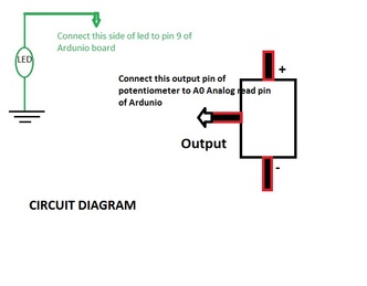
Coming to the circuit diagram. Apply 5 volts to 12 volts to the +Pin(anode) of the potentiometer and connect -Pin(cathode) to ground. Connect the potentiometer output pin to the ardunio analog input Pin-A0. Now connect the led +pin (anode) to pin no. 9 of the Ardunio. Pin #9 is used as the analog output pin. Few pins of Arduino uno can be used to generate variable voltage and pin no.9 is one of them. It outputs analog values in the form of PWM (Pulse Width Modulated Signal). Connect the other end of the LED to ground in series with a resistor. Resistance can be in the range of 120 ohm to 4.7 k ohm. Make the circuit and upload the sketch to your ardunio uno.
Voltage variation disappears LED
When you turn the potentiometer knob, the resistance decreases and current begins to flow. As the current increases, the voltage increases and there is a change in voltage that is detected by the Arduino analog input pin A0. We analyze this change in voltage in our sketch (code) and then send the change to pin #9 that our LED is connected to. The LED disappears when we constantly turn the potentiometer knob clockwise and counterclockwise.
Project code
It is necessary to divide the analog reading by 4 because analog writing function generates analog values between 0 and 255. Where 0 represents low and 255 represents high, and analog reading inserts the value from 0 to 1023. Finally the analog writing function generates the value analog. Now you will see the LED fading/brightness varying if you turn the potentiometer knob.