This tutorial will teach you how to control a Robo car using any Wifi enabled device.
Required components:
1. ESP 8266 Wi-Fi ModuleAbout ESP8266
ESP 8266 is the latest thing on the internet. It's a Wifi module a little bigger than a 1 Re coin. Well, that's not why he's famous. What has made it very popular among electronics enthusiasts is its incredibly low cost. I bought it for just $5 (~300 Rs). An Arduino along with a Wifi shield would cost 10 times the cost of this module.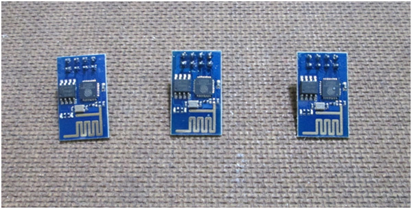
Fig. 1: Image showing ESP8266 Wi-Fi modules
It can be interconnected with any microcontroller through USART communication, which means that it only needs the RX and TX pins. Another feather to the hat was recently added. The developer has released the SDK files of the module and hence even the module can be reprogrammed and its GPIO pins can be used independently without any additional microcontroller. But that's beyond the scope of this tutorial. We would be using the module along with Arduino UNO.
Making a Breadboard Adapter for the ESP8266 Module:
The problem with the physical feature of the module is that you cannot connect it directly to a breadboard. So I decided to make an adapter that will be used to connect the module to a breadboard. These are the parts you would need to make the adapter: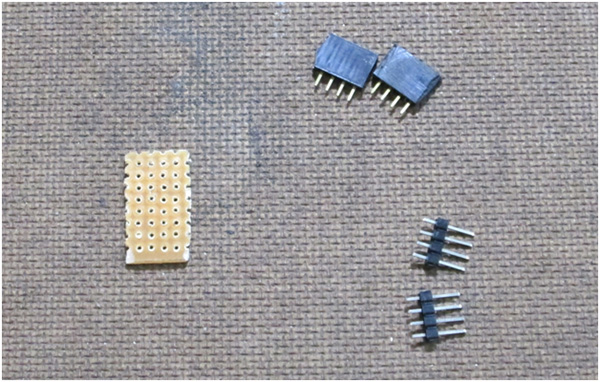
Figure 2: Image showing the components needed to make the ESP8266 modem breadboard adapter
Start by soldering the female connector to the PCB. Solder the corner pins first so that the header fits properly on the PCB. Then solder the remaining 4 pins.
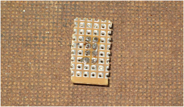
Fig. 3: Image showing breadboard adapter PCB soldered to fit ESP8266 modem female header
Then place the male connectors on the opposite side of the PCB and carefully solder them to the PCB.
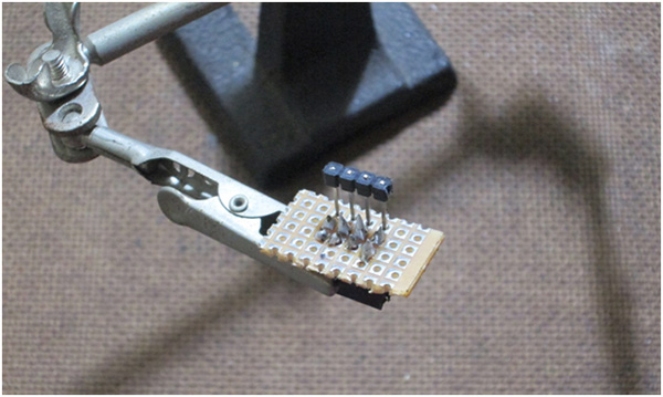
Figure 4: Image showing the male header placed on the ESP8266 modem breadboard adapter
After soldering, you can remove the black plastic piece attached to the male connector and begin soldering each male pin to the corresponding female pin. In the end you would have something like this:
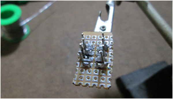
Fig. 5: Image showing the male connector soldered onto the ESP8266 modem breadboard adapter
Once you do this, you can plug it into a breadboard and connect the ESP 8266 module to it easily.
Here is a detailed video tutorial showing the process: (Optional)
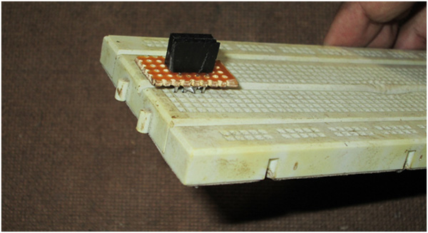
Figure 6: Image showing the ESP8266 modem breadboard adapter placed on a breadboard
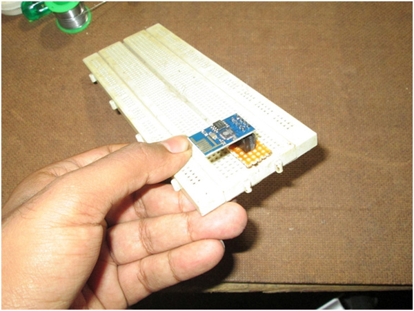
Figure 7: Image showing the ESP8266 Wi-Fi module placed on the breadboard
AT commands for ESP 8266:
|
Command |
Description |
|
AT+GMR |
To find out the firmware version |
|
AT+RST |
To reset the module |
|
AT+CWMODE |
To set the mode of operation, i.e. as access point or station mode or both. |
|
AT+CWLAP |
To see the list of available APs |
|
AT+CIPSERVER |
To set as server |
|
AT+CIPMUX |
To choose between single or multiple connections |
|
AT+CIPSEND |
To set channel number, data length and send data over WiFi |
|
AT+CYPCLOSIS |
To close the connection |
Server on ESP 8266:
We will be sending a web interface (an HTML page) to any device (say a Wifi enabled mobile phone) connected to the Wifi module. The HTML page code would be provided by Arduino. And also, Arduino would decode the request from the device and control the motors accordingly. As the Wifi module can also function as an access point, we do not need an extra wireless router for the project. If you have no idea about HTML pages, go to my project “Controlling Appliances over Wifi and Ethernet” and learn the basics. Here is the algorithm to be followed to configure a server on ESP 8266:Algorithm:
– Test module using the “AT” command – Set the operating mode using the command “AT+CWMODE=Hardware configuration:
Gather all the pieces shown in the image.
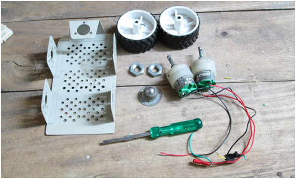
Figure 8: Image showing the components needed to make the robot
Attach the engines to the chassis and then the wheels to the axle.
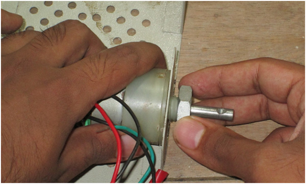
Figure 9: Image showing the metal structure of the robot connected to the DC motor
Use some screws and nuts to fix the spinning wheel
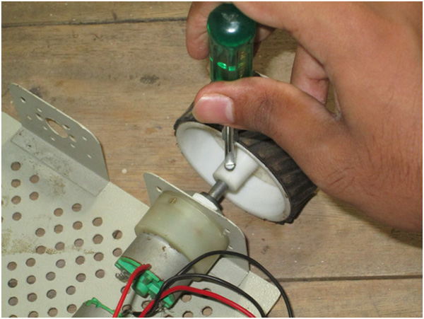
Figure 10: Image showing wheels connected to DC motors on the Robot
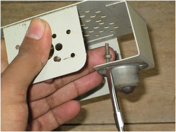
Figure 11: Image of the rotating wheel attached to the front of the Robot Car
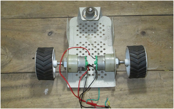
Figure 12:
Code explanation:
– Define pins 8, 9, 10 and 11 as output pins and serial communication with a baud rate of 9600 bps. – Send the “AT” command to the module. – Set the operation mode to station and access point using the command “AT+CWMODE=3” – Set the connection mode to multiple connections by sending “AT+CIPMUX=1” – Put the module in Server mode and use the default port sending “AT+CIPSERVER=1, 80” – Enter infinite loop and check for incoming Wifi requests – If a request was made, read the request and store the channel number where the request originated – Send the HTML page code to the stored channel number using the commands “AT+CIPSEND=Setup Instructions
-Connect everything according to the circuit diagram and turn on the entire system.
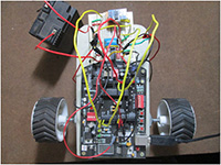
Fig. 13: Simple robotic car prototype
– Wait a few seconds for Wifi and Arduino to initialize. After about 30 seconds, activate Wifi on your device (mobile, tablet or laptop) and you will see some available networks.
– You can connect to your home network (which is “ Robots Recharged ” in my case and that’s what I’m going to connect to) or to the access point itself (which is “ ESP_9F0F14 ” in my case. The SSID of the module is nothing more is than your name followed by the last 6 characters of your MAC address)
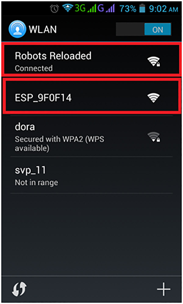
Figure 14: Arduino-based control circuit prototype mounted on robotic car
– Then open your browser and enter the IP address
1. From the module on the home network if you are connected to the home network (like me and in my case it is 192.168.0.101 or 192.168.0.102 ) Or 2. 192.168.1.4 if you connect to the access point named “ESP_<last 6 characters of MAC address>” In a moment you should see a page like this in your browser: Now click on the links and you will see the engine start moving. If they are moving in the wrong direction, check the connections and change them if necessary.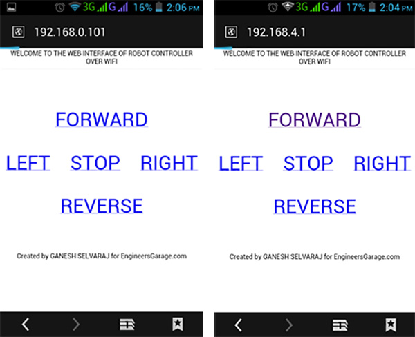
Figure 15: Screenshot of Wi-Fi connections on Android phone showing ESP module hotspot
– You can connect to your home network (which is “Robots Reloaded” in my case and that is what I will connect to) or to the Access Point itself (which is “ESP_9F0F14” in my case. The SSID of the module is nothing more is than your name followed by the last 6 characters of your MAC address)
Project source code
#define esp Serial
"); esp.print("
FORWARD
LEFT STOP "); esp.print("RIGHTREVERSE
Created by GANESH SELVARAJ for EngineersGarage.com
"); delay(5000); esp.print(F("AT+CIPCLOSE=")); esp.println(ch_id);} void forward { digitalWrite(in1,HIGH); digitalWrite(in2,LOW); digitalWrite( in3,HIGH); digitalWrite(in4,LOW);}void reverse { digitalWrite(in1,LOW); digitalWrite(in2,HIGH); digitalWrite(in4,HIGH);}void right { digitalWrite( in1,HIGH); digitalWrite(in2,LOW); digitalWrite(in2,LOW); ; digitalWrite(in4,LOW);}void stop_bot { digitalWrite(in1,LOW); digitalWrite(in3,LOW);
Circuit diagrams
| Circuit Diagram-Arduino-ESP8266-Ased-Module-Wi-Fi-Controlled-Robotic-Car | 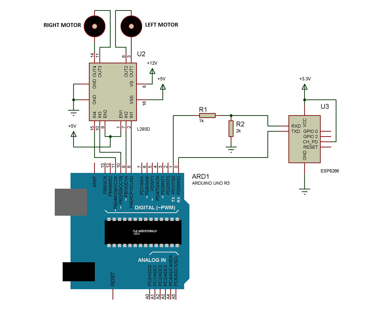 |

