The previous article explains serial communication using 8-bit data transfer. The AVR microcontroller also supports serial data transfer with frame size of 5, 6, 7 and 9 data bits. The size of the data frame can be adjusted according to the application. For example, consider a system that needs to transmit only ASCII codes as data. In this case, the data frame size of 7 bits is sufficient because the ASCII code data length is equal to 7 bits. This will make the system more efficient, saving time by one clock period on each data frame transmission. This article explains serial data transfer with different frame sizes.
The data frame size can be selected by setting the UCSZ (USART Character Size) bits. The UCSRC register contains UCSZ bits (1:0) and UCSRB contains UCSZ2 bits. The following table shows the UCSZ bit settings corresponding to different data frame sizes.

Fig. 2: UCSZ bit configuration for serial communication of different data frame sizes
Schedule:
Case 1: Frame size 5, 6 and 7 bits:
These three frame sizes can be selected by programming just the UCSZ1 and UCSZ0 bits. There is no need to program the UCSZ2 bit because the default value of this bit is zero.
For example: UCSRC= (1<
// No parity, 1 stop bit.
The programming steps for sending and receiving data will remain the same as those used for transmitting and receiving 8-bit data. For more information, readers can refer to the previous article on serial communication .
Test program for 6-bit reception and transmission:
A test program is written for 6 bit data communication between Microcontroller and PC. In this experiment, input is obtained from the user via a keyboard. The corresponding data is sent to the microcontroller through the PC's COM port. The microcontroller receives the data and returns it back to the PC's COM port. HyperTerminal is used to configure the COM port to make it compatible with this experiment.
The following steps are used to configure COM ports:
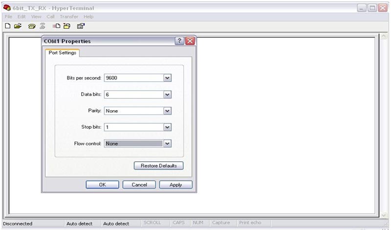
1. Set Baud Rate = 9600 bps, Data Bit=6, Parity=None, Stop Bit=1.

Fig. 3: Configure COM ports for serial communication
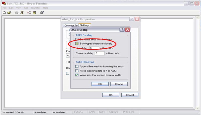
2. Select the check box corresponding to Echo as shown in the following image to observe data transmission and reception.

Exit:
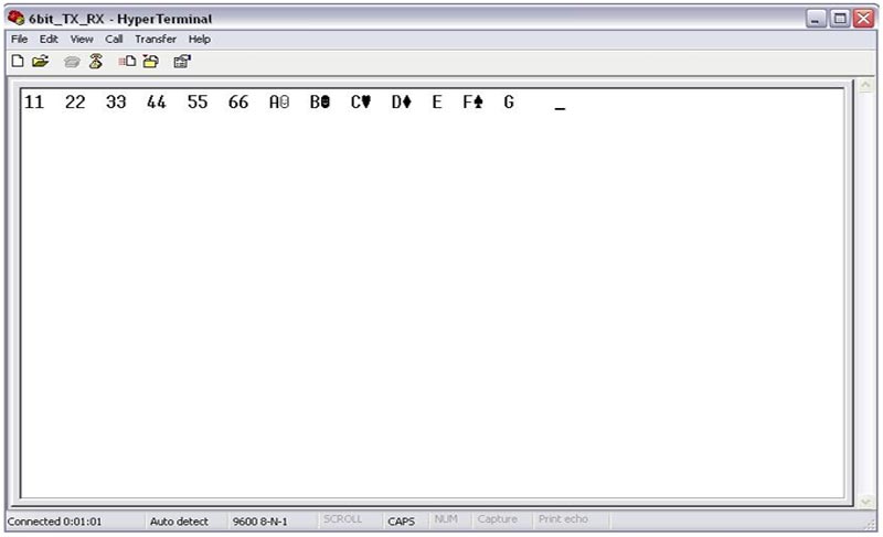
The following output is received when 1 2 3 4 5 6 ABCDEFG keys are pressed on the keyboard.

Fig. 5: Serial communication output between AVR and PC
As shown in the image above, proper output is received when numeric keys are pressed, but when alphabetic keys are pressed, some symbol appears. This unexpected output is received because we are working with 6-bit data frame size. If the 6-bit data frame is selected, two most significant bits will be masked to zero when reading the UDR. The ASCII code of '1' is 0x31 (0011 0001). If the two most significant bits are masked, 11 0001 remains, which is also equal to 0x31. The size of ASCII codes for all numeric values is 6 bits, so there will be no problems in receiving and transmitting numeric values in 6-bit mode. But the ASCII value of 'A' is 0x41 (0100 0001). If two most significant bits are masked, you will be left with 00 0001, which is equal to 0x01, so some unusual symbol will be printed.
Case2: 9-bit frame size:
9-bit data communication can be used in multiprocessor communication. To select the 9-bit data frame, all UCSZ bits are set to 1(UCSZ (2:0) =7).
For example:
UCSRB=(1<
UCSRC=(1<
1. 9-bit data transmission:
9-bit data must be buffered before transmission. Since the data size of the UDR register is only 8 bits, the ninth bit must be stored in the TXB8 bit of the UCSRB register before the lower byte is stored in the UDR.
void usert_tx(unsigned int serial_data) //function transmission{
2. 9-bit data reception:
The ninth bit must be read from the RXB8 bit before reading the lower byte. The status of FE (Frame Error), DOR (Data Over Run) and PE (Parity Error) should also be checked to verify the data.
unsigned int usert_rx(void) // function for reception
{
while(!(UCSRA & (1<
if(UCSRA & ((1<
return -1;
UCSRB =(UCSRB>>1)&0x01; //filter 9 bits
return ((UCSRB<<8) UDR); // return value
}
Project source code
 ###

 // Program for serial communication (USART) with different frame sizes using AVR microcontroller
###
Circuit diagrams
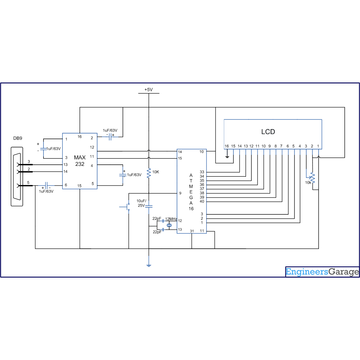
| Serial-USART Communication Circuit Diagram with Different Frame Size Using AVR Microcontroller |  |
Project Components
- ATmega16
- LCD
- MAX232

