This article presents the concept of interrupts and the different types of interrupts in the AVR (ATmega16) microcontroller. Interrupt as the name suggests, interrupts the current routine of the microcontroller. The microcontroller executes instructions in a sequence according to the programs. Sometimes there may be a need to instantly deal with higher priority, planned events that may occur during normal operations. To deal with this type of event, AVR microcontrollers are equipped with Interrupt Systems.
When an interrupt occurs, the normal flow of instructions is suspended by the microcontroller and the code corresponding to the interrupt that occurred is executed. Once the code corresponding to the interrupt has been completely executed, execution resumes from the same instruction where it was interrupted.
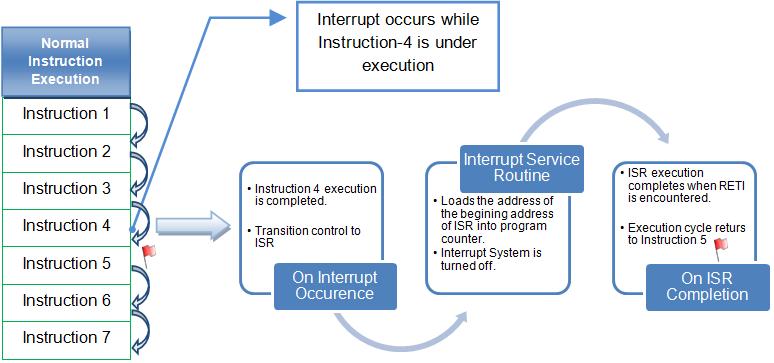
Following is what happens when an outage occurs:
1. The microcontroller normally completes the instruction being executed.
two. Program control is transferred to the Interrupt Service Routine (ISR). Each interrupt has an associated ISR, which is a piece of code that tells the microcontroller what to do when an interrupt occurs.
3. ISR execution is performed by loading the start address of the corresponding ISR into the program counter.
4. ISR execution continues until the return interrupt instruction (RETI) is encountered.
5. When the ISR is complete, the microcontroller resumes processing where it left off before the interrupt occurred, i.e., program control reverts to the main program.
The entire process can be visualized in the following flowchart:

Fig. 2: Block diagram of the common interrupt process
Atmega16 outages
The number of interrupts available varies depending on the different microcontrollers in the AVR family. The Atmega16 has a total of twenty-one (21) interrupts available. Available interrupts are categorized into two classes:
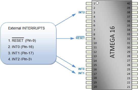
1. External Interrupts- Out of the twenty-one available interrupts, four interrupts are present directly on the controller pins to deal with the interrupts generated by external sources, hence they are called external interrupts. The four available interrupts and their respective pins are shown in the figure below in order of priority:

Fig. 3: External interrupt pin configuration on the AVR
two. Internal Interrupts- The remaining seventeen (17) interrupts are available for internal use and support accurate and efficient operation of various peripherals like ADC, timers and USARTs, etc. The table below describes the available internal interrupts in order of priority:
|
S. No.
|
INTERRUPT
|
DEFINITION
|
|
1
|
COMP. TIMER2
|
Timer/Counter2 Compare start interrupt
|
|
two.
|
TIMER2 OVF
|
Timer2 overflow interrupt
|
|
3.
|
TIMER1 CAPT.
|
Timer/counter1 capture event interrupt
|
|
4.
|
COMPA. TIMER
|
Timer/Counter1 Compare Match An interrupt
|
|
5.
|
COMPB TIMER.
|
Interruption of timer/counter comparison correspondence B
|
|
6.
|
TIMER1 OVF
|
Timer/counter1 overflow interrupt
|
|
7.
|
TIMER0 OVF
|
Timer/counter overflow interrupt0
|
|
8.
|
SPI, STC
|
Complete interruption of serial transfer
|
|
9.
|
USART,RXC
|
USART receives complete outage
|
|
10.
|
USART, UDRE
|
USART data logging empty interrupt
|
|
11.
|
USART, TXC
|
Complete interruption of USART transmission
|
|
12.
|
ADC
|
Complete ADC conversion stop
|
|
13.
|
EE_RDY
|
EEPROM Ready Interrupt
|
|
14.
|
ANA_COMP
|
Analog Comparator Interruption
|
|
15.
|
TWI
|
Two-wire serial interface interrupt
|
|
16.
|
TIMER0 COMP.
|
Timer/countrt0 comparison start interrupt
|
|
17.
|
SPM_RDY
|
Store read interrupt in program memory
|
Fig. 4: Internal interrupt pin configuration on the AVR
Internal interrupts will be discussed with their respective peripherals. External interrupts are primarily focused on in this article.
External interrupt configuration registers:
To configure an external interrupt INT0, INT1 or INT2, it is necessary to initialize the respective interrupt by making appropriate bit settings of the following 4 registers. The scope of this document is limited to the explanation of the bits corresponding only to interrupts, the detailed description of the other bits of these registers can be found in the Atmega16 datasheet.
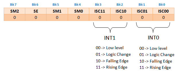
1. MCUCR (MCU Control Register)

Fig. 5: MCUCR register bit value to configure the AVR external interrupt
Bit0, Bit1, Bit2 and Bit3 of the MCUCR register determine the nature of the signal on which interrupt 0 (INT0) and interrupt 1 (INT1) are to occur.
two. MCUCSR (MCU Control and Status Register)

Fig. 6: MCUCSR register bit value to configure the AVR external interrupt
Bit6 of the MCUCSR register determines the nature of the signal on which external interrupt 2 (INT2) should occur. INT2 is only edge triggered, it cannot be used for level triggering like INT0 and INT1.
3. GICR (General Interruption Control Register)

Fig. 7: Bit value of the GICR register to disable/enable the respective interrupt in the AVR
GICR registers Bit5, Bit6 and Bit7 called interrupt masks are used to disable/enable the respective interrupt. The interrupt is disabled when the bit value is set to 0 and enabled when the bit value is set to 1. By default, all interrupts are disabled.
The three registers mentioned above must be configured accordingly to initialize a specific interrupt. Also note that in addition to the registers mentioned above, the Ibit (Bit7, Global Interrupt Enable) of SREG register must also be set to 1. If the global interrupt enable bit is set to 0, none of the interrupts will work regardless other registry settings. The activation and clearing of bit I is done by SEI and CLI instructions.
Programming steps:
To schedule an interruption, the following steps must be followed:
1. Clear the global interrupt enable bit in the SREG register.
two. Initialize the interrupt by properly configuring the MCUCR, MCUCSR, and GICR registers.
3. Set the Global Interrupt Enable bit in the SREG register.
4. Define the appropriate interrupt service routine (ISR) for the interrupt.
There are two ways to write ISR, for example, ISR for INT0 can be written in the following two ways:
A. ISR (INT0_vect)
B. SIGNAL (SIG_INTERRUPT0)
Example: Let's write a simple code to make an interrupt work. Initialize INT0 to generate interrupt on rising edge trigger. The interruption is generated through buttons that alternate the status of the LEDs connected to the PORTA. The connections of the LEDs to the controller are shown in the circuit diagram.
Therefore, to enable INT0 it is necessary to set Bit6 of the GICR register, that is,
GICR= (1<
For INT0 rising edge trigger, Bit0 and Bit1 status will be-
ISC00 (Bit0) = 1
ISC01 (Bit1) = 1
ISC00 (Bit0) = 1
ISC01 (Bit1) = 1
So, MCUCR=(3<
Project source code
 ###

// Program to use external interrupts (hardware) from the AVR microcontroller (ATmega16)
###
Circuit diagrams
| Circuit diagram of how to use external hardware interrupts of AVR-ATmega16 microcontroller |  |
Project Components
- ATmega16

