Como fazer a interface do teclado com o microcontrolador AVR (ATmega16) – (Parte 11/46)

How to interface the keyboard with the AVR microcontroller (ATmega16) – (Part 11/46)

Keyboard is the most widely used input device to provide information from the external world to the microcontroller. The keyboard makes the application more interactive for users. The concept of interfacing a keyboard with the ATmega16 is similar to interfacing with any other microcontroller. The article Keyboard interface with 8051 can be consulted for a detailed description of the methodology used here. This article explains interfacing a 4x3 keyboard with the AVR microcontroller (ATmega16) and displaying the output on an LCD.
The algorithm and detailed explanation of the keyboard interface are provided in the article mentioned above. The brief steps to connect the keyboard to the AVR are outlined below:
1. Configure row or column pins.
two. Set all output pins low and input pins high.
3. Continue monitoring the value of the port where the keyboard is connected.


 while(1)

{ PORTD=0xF0; //sets all inputs as one value=PIND; //gets the PORTD value in the “value” variable if(value!=0xf0) //if any key is pressed, the value will change { check1; check2; check3; check4; } }
4. If there is any change in the port value, set one of the port output pins to zero and leave everything high.


 null check 1 (null)
 {
 //DDRD = 0xf0;
 block =0b11111110;
 //pad &= (0< 
_delay_us(10);
 if(bit_is_clear(PIND,c1))
 LCD_write('1');
 else if(bit_is_clear(PIND,c2))
 LCD_write('2');
 else if(bit_is_clear(PIND,c3))
 LCD_write('3');
 }
 
5. If any input pin is zero, write the specific pin data to the LCD, otherwise continue with step (4).

Project source code

###


 // Program to take keyboard input and display it on the LCD.
#include
#include #define pad PORTD #define r1 PD0 #define r2 PD1 #define r3 PD2 #define r4 PD3 #define c1 PD4 #define c2 PD5 #define c3 PD6 check null1 (void); check null2 (void); check null3 (void); check null4 (void); #define LCD_DATA PORT //LCD data port #define ctrl PORTAB #define in PB2 //activate the signal #define rw PB1 //read/write signal #define lol PB0 //resistance selection signal void LCD_cmd(unsigned char cmd); empty init_LCD(empty); void LCD_write (unsigned character data); unsigned internal press; main int { unsigned character value; DDRA=0xff; //LCD_DATA port as output port DDRB=0x07; //flag as exit DDRD=0x0F; block=0xf0; init_LCD ; //LCD initialization LCD_write_string("press a key"); LCD_cmd(0xc0); while(1) { PORTD=0xF0; //sets all inputs as one value=PIND; //gets the PORTD value in the “value” variable if(value!=0xf0) //if any key is pressed the value will change { check1; check2; check3; check4; } } return 0; } null check 1 (null) { //DDRD = 0xf0; block =0b11111110; //pad &= (0< _delay_us(10); if(bit_is_clear(PIND,c1)) LCD_write('1'); else if(bit_is_clear(PIND,c2)) LCD_write('2'); else if(bit_is_clear(PIND,c3)) LCD_write('3'); } null check 2 (void) { block=0b11111101; /pad &= (0< _delay_us(10); if(bit_is_clear(PIND,c1)) LCD_write('4'); else if(bit_is_clear(PIND,c2)) LCD_write('5'); else if(bit_is_clear(PIND,c3)) LCD_write('6'); } null3 check (void) { block=0b11111011; //pad &= (0< _delay_us(10); if(bit_is_clear(PIND,c1)) LCD_write('7'); else if(bit_is_clear(PIND,c2)) LCD_write('8'); else if(bit_is_clear(PIND,c3)) LCD_write('9'); } null check 4 (null) { block =0b11110111; //pad &= (0< _delay_us(10); if(bit_is_clear(PIND,c1)) LCD_write('#'); else if(bit_is_clear(PIND,c2)) LCD_write('0'); else if(bit_is_clear(PIND,c3)) LCD_write('*'); } empty init_LCD(empty) { LCD_cmd(0x38); //initialization of the 16X2 LCD in 8-bit mode _delay_ms(1); LCD_cmd(0x01); //clean the LCD _delay_ms(1); LCD_cmd(0x0E); //cursor ON _delay_ms(1); LCD_cmd(0x80); // ---8 goes to the first line and --0 is to the 0th position _delay_ms(1); turn back; } void LCD_cmd (unsigned char cmd) { LCD_DATA=cmd; ctrl=(0< //making RS and RW as LOW and EN as HIGH _delay_ms(1); ctrl=(0< //making RS, RW, LOW and EN as LOW _delay_ms(50); turn back; } void LCD_write (unsigned character data) { LCD_DATA=data; ctrl = (1< // making RW as LOW and RS, EN as HIGH _delay_ms(1); ctrl = (1< //making EN and RW as LOW and RS HIGH _delay_ms(50); // gives a 10 millisecond delay to run things turn back ; } void LCD_write_string(unsigned character *str) // get the value of the string address in the pioneer *str { int i=0; while(str(i)!='�') // the loop will continue until NULL characters are in the string { LCD_write(str(i)); //sending data to the CD byte by byte me++; } turn back; }

###

Circuit diagrams

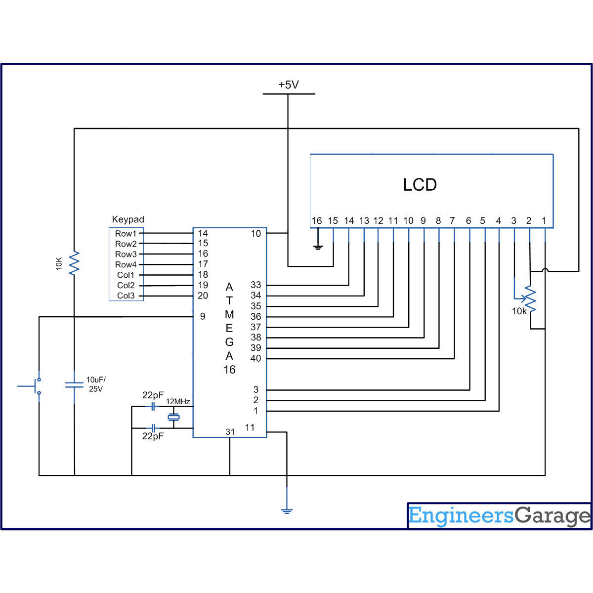
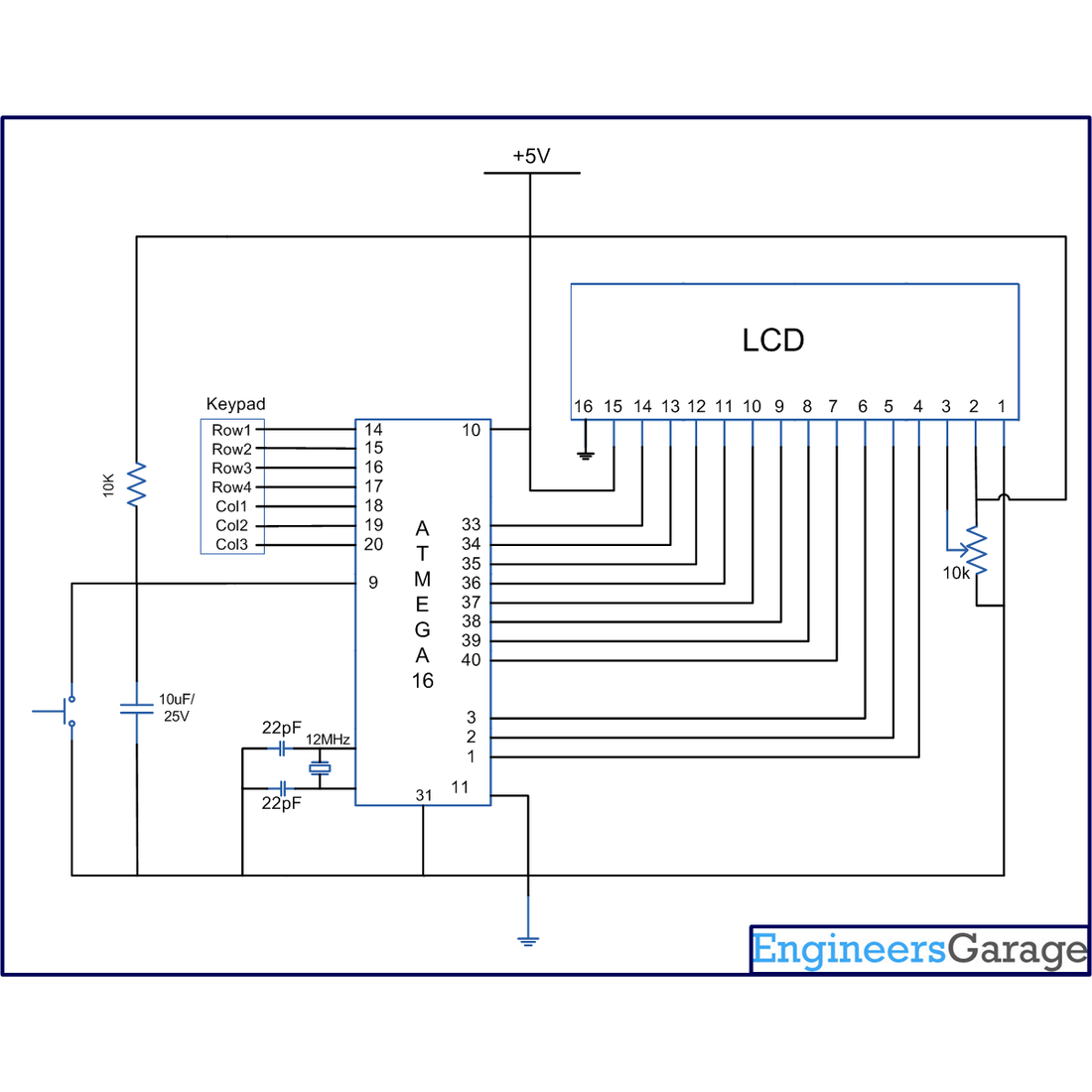
Circuit diagram of how to interface the keyboard with the AVR-ATmega16 microcontroller

Project Components

  • ATmega16
  • LCD
  • Default

Project video

Conteúdo Relacionado

A network of sensors is embedded in every vehicle,...
The motor controller is one of the most important...
ESP32-CAM is a compact camera module that combines the...
A evolução dos padrões USB foi fundamental para moldar...
A SCHURTER anuncia um aprimoramento para sua conhecida série...
A Sealevel Systems anuncia o lançamento da Interface Serial...
A STMicroelectronics introduziu Diodos retificadores Schottky de trincheira de...
Determinar uma localização precisa é necessário em várias indústrias...
O novo VIPerGaN50 da STMicroelectronics simplifica a construção de...
A Samsung Electronics, fornecedora de tecnologia de memória avançada,...
O mercado embarcado tem uma necessidade de soluções de...
You have probably come across the term ' drag...
You probably have a support insulator if you've noticed...
You've probably seen stand an insulator sit on power...
You've probably seen shackle insulators enthroned on electricity poles,...
You have probably experienced situations where controlling a circuit...
Back to blog

Leave a comment

Please note, comments need to be approved before they are published.