Inductors are simple components in electronic devices that perform tasks such as cleaning electrical signals, helping with timing, and managing power. They store energy in magnetic fields when electricity flows through them and releases them back into the circuit. Inductors resist sudden changes in the flow of electricity by pushing “spikes” by creating an electrical force (like a small electrical push or pull), according to a rule called Lenz's Law.
Inductors are measured in the “Henry” unit (H), named after an influential scientist, and this exemplifies how much energy they can store. But they interact differently depending on the signal, as shown in the examples below.
- For regular DC electrical signals, inductors act as a shortcut, allowing electricity to flow easily
- For AC signals, inductors are like an obstacle, making it difficult for electricity to pass through.
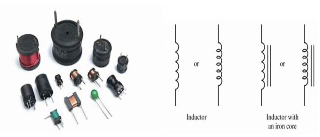
Typical images of inductors.
There are several important parameters to consider when selecting an inductor.
- The Q Factor or Quality Factor measures the reliability of an inductor in doing its job in an electrical circuit. Evaluates the efficiency of the inductor at a specific frequency, evaluating its performance. A high Q factor means the inductor is excellent at its job, ensuring the circuit operates accurately at a specific frequency.

- Self-Resonant Frequency ( SRF) occurs when an inductor does not function properly. In radio frequency (RF) circuits, it is essential to choose an SRF higher than the frequency at which the circuit operates. This is because in SRF, both the inductance and Q Factor become zero. Therefore, the inductor will not help the circuit at its self-resonant frequency. The ideal is to avoid using it at this frequency.
- Saturation current is the maximum amount of constant electrical current that an inductor can withstand before losing effectiveness. The core of an inductor can only contain a certain amount of magnetic force. When exceeding this limit, the inductor will no longer function correctly. While Rated Current is the maximum amount of current that can be safely sent through an inductor without causing damage, Saturation Current is the limit. At this point, the inductor will fail.
- DC Resistance (DCR) is like the natural resistance found in inductor wire. Think of it as a small resistor built into the inductor wire. This resistance is essential to consider when designing DC-DC converters because it causes electrical energy to transform into heat, causing energy loss. The higher the DCR, the less efficient the inductor is at transferring electrical energy and the more heat (power) is wasted.
- Tolerance measures how much the “inductance” of an inductor can deviate or differ from the data sheet. When there is a tolerance, it means that the inductor may not perform exactly as expected. This difference can lead to an unintended change in the frequency at which the inductor is expected to operate. This is particularly important for RF filters, which must be extremely precise. Therefore, tolerance is critical because it can affect the functioning of a circuit.
What are converters?
DC to DC converters are like magic transformers for electricity. They can change one level of electrical energy to another. Electronic devices, such as computer chips and transistors, need specific amounts of electricity to function properly. Sometimes they require more voltage and other times less.
Think of a buck converter as a power reducer, while a boost converter is like a power amplifier. Converters make electronic circuits work better by using electricity more efficiently, reducing any power gaps and responding to changes in electrical load.
Choosing the ideal components based on the circuit requirements is important for an effective and efficient device. Often this means tuning the standard circuit to meet the specific requirements of each component.
The working principles of a DC-DC converter
The operation of a DC to DC converter is simple. When a switch is turned on, the inductor (found at the input of the circuit) allows energy to enter and stores it as magnetic energy. When the switch is turned off, the inductor releases the stored energy.
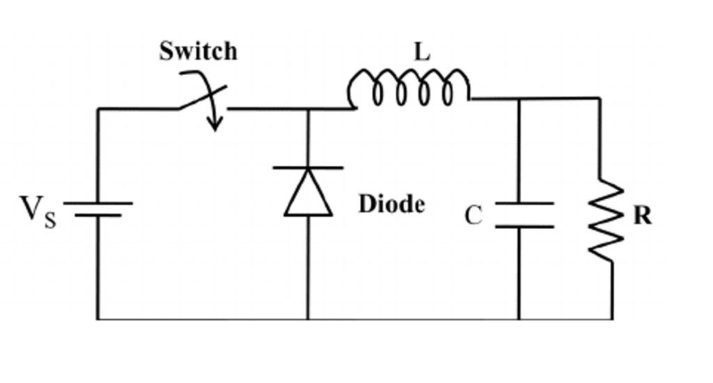
The working principles of a DC-DC converter.
Selecting an Inductor for Vehicle DC-DC Converters
Objective: Demonstrate how to choose an inductor for a DC-DC converter in a real-life scenario.
The DC-DC converter in vehicles plays a significant role. It takes high-voltage energy from the vehicle's battery and transforms it into low-voltage energy. This low-voltage power operates features such as the vehicle's lights, windshield wipers, and window controls. This applies to fully electric and hybrid cars.
It may be important to keep the vehicle's high-voltage and low-voltage parts separate, especially if they are used independently. The converter used may differ depending on the requirements.
- To increase or decrease the voltage, a buck-boost converter is used.
- If the voltage needs to be inverted, a charge pump converter is used.
These converters help the vehicle's electrical system run smoothly and safely.
In automotive applications, the standard electrical voltage is 48 volts, which must be converted or reduced for various purposes. To illustrate, let's consider the LM5007 Integrated Circuit (IC), which operates as a DC to DC buck converter.
The LM5007 regulator is like a simple tool that can change high voltages from nine to 75 volts to lower voltages. It works well with 12, 24 or 48 volt power sources, whether those sources are well controlled or unstable.
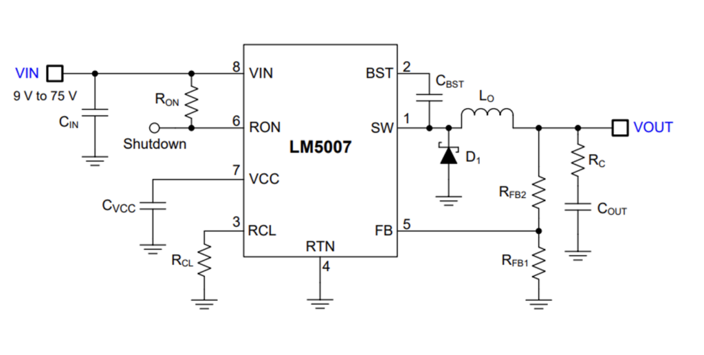
A typical application scheme.
Design requirements : The parameters are below, from which we can derive the rest.
Input voltage = 48V
Output voltage = 12V
Maximum output current = 500mA
Nominal switching frequency = 380 kHz
Let's set the switching frequency through the RON resistor:
R ON = V out / 1.42 × 10 -10 F sw
R ON = 12V / 1.42 × 10 -10 × 380×10 3
R ABOUT = 222 kW
Selecting FSW = 380 kHz results in RON = 222 kΩ. Choose a default value of 200 kΩ for this project.
To calculate the buck inductor (L1), the inductor current ripple is:
∆I I = (V IN –V OUT )V OUT /I 0 F sw V IN
The peak-to-peak inductor ripple current ΔIL is 50% x I OFF (max.)
I 0 = (V IN –V OUT )V OUT /∆I I F sw V IN
l 0 = 103µH
i 0 is 103 µH, so we can select a default inductor value of 100 µH.
Let's calculate the value of the series resistor R c :
R c = 25mV×V OFF / ∆I L(min) ×V REFERENCE
Typical value of V REFERENCE is 2.5V and ∆I L (minimum) is 88mA according to the datasheet, so…
Rc = 1.36Ω
Based on the calculated value of R c is 1.36Ω, select a default value of 1 Ω.
Next, let's select the output capacitor to minimize capacitive ripple:
C OUT = ∆I I / 8×F SO ×∆V COUT
ΔV COUT is the voltage ripple across the capacitor which is 10mV.
C OFF = 7.5 µF
C OUT = 7.5 µF, so select a default value of 15 µF for C OUT with dielectric X5R or X7R and nominal voltage 16 V or greater.
Now let's calculate the feedback resistors, RFB1 and RFB2:
VOUT = VFB x (RFB2/RFB1 + 1), and since VFB = 2.5 V (according to data sheet) in regulation, the ratio of RFB2 to RFB1 is 3: 1. Select default values of RFB1 = 1 kΩ and RFB2 = 3.01 kΩ. Other values can be chosen as long as the 3:1 ratio is maintained.
RFB1 = 1 kΩ
RFB2 = 3.01 kΩ
Note: These calculations are tailored specifically for this IC and are applicable exclusively to this converter. Separate calculations will be required for other converter models.
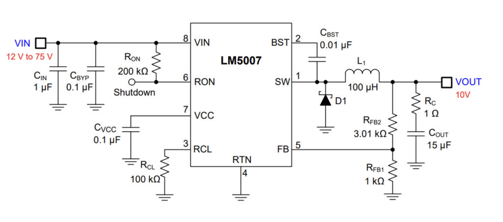
Circuit Schematic: Selecting an Inductor for Vehicle DC-DC Converters.
Forms
Renewable Energy: When using DC to DC converters for renewable systems, the power must remain smooth without sudden variations. Converters ensure that the energy is stable. They must also be flexible and work with different types of energy sources, such as solar panels or wind turbines.
Medical Devices: Isolated DC to DC converters are essential when safety is a concern. They help keep output power separate from dangerous electricity on the input side.
However, depending on the device, non-isolated converters are sometimes preferred. This is true for powering x-ray machines, where safety is managed differently. These converters are acceptable when there is no risk of mixing electricity with the output power.
Smart lighting: Often uses special devices to control energy efficiently, such as LEDs. These devices must manage the flow of electricity, protect against voltage, and allow easy control using PWM (Pulse Width Modulation). They should also have a simple design.
For this to occur, linear regulators, charge pumps and regular switch-based converters are typically used. These converters act as controllers for the LED lights, ensuring that they function and are easily managed.
Choosing the ideal converter is like using the right tool for the job.
Conclusion
When considering inductors used in DC to DC converters, you can look to general numbers to describe how they work. However, it is essential to keep in mind that these numbers are like photos taken under specific conditions. They may not show the entire story of an inductor's performance in all situations. Therefore, it is vital to take into account the changes in behavior of each specific inducer in different situations.