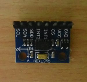
In the previous tutorial we covered the I2C Bus on Arduino. We also learned how to use the wire library to communicate with interintegrated circuit or I2C devices using Arduino boards.
The I2C bus is commonly used by digital sensors. By using this interface, hundreds of slave devices can be connected on just two wires. Each device – whether an I2C master or slave – requires only two channels to connect to the bus.
Although this is a slow data communication protocol, its simplicity makes the I2C bus one of the most popular interfaces among digital sensors. Typically, sensors only use other communication interfaces (such as UART or SPI) when full-duplex communication is strictly required. Otherwise, I2C is the de facto serial interface for all digital sensors.
Some examples of sensors that use an I2C/TWI bus include: ADXL345 accelerometer, L3G4200D gyroscope, MC5883L magnetometer, BMP180 pressure sensor, and DS1307 RTC.
In this tutorial, we will learn how to interface an ADXL345 Accelerometer sensor with Arduino using the I2C/TWI bus.
The ADXL345 accelerometer
ADXL345 is a three-axis MEMS accelerometer sensor. It's also digital inertial sensor that uses a capacitive accelerometer design.
Features include:
- A user selectable range of up to +/-16g
- A maximum output resolution of 13 bits
- A sensitivity of 3.9 mg/LSB
- A maximum output data rate of 3200 Hz
The sensor has I2C and SPI interfaces to communicate with controllers or computers.
The ADXL345 measures static acceleration due to gravity and dynamic acceleration resulting from movement or shock. It can be used to detect linear acceleration in three axes, detecting the tilt and free fall of an object.
There are two interrupt pins along with I2C and SPI interfaces on the sensor. This is where various built-in sensing functions such as free fall, single tap and double tap can be mapped. The ADXL345 can also detect the presence or lack of relative motion by comparing acceleration values to user-defined thresholds.
As a digital sensor, the ADXL345 has built-in registers that can be read and written to configure settings and read acceleration values. It offers four measurement ranges: +/-2g, +/-4g, +/-8g and +/-16g.
The default measurement range is +/-2g, which can be used to detect acceleration of up to 19.6 m/s2 in any direction along each axis.
The maximum resolutions are:
- 10 bits for +/-2g
- 11 bits for +/-4g
- 12 bits for +/-8g
- 13 bits for +/-16g range
The default resolution is 10 bits. For the +/-2g range (default), it allows a sensitivity of 3.9mg/LSB. The default data rate is 100 Hz. All of these settings can be changed or configured by writing data to the ADXL345's built-in registers. A controller/computer can read the acceleration by simply reading the values from registers 0x32 to 0x37.
ADXL345 interface with Arduino
The ADXL345 sensor has I2C and SPI interfaces to communicate with any controller or computer. The sensor supports three-wire and four-wire SPI. In addition to these serial interfaces, sensor interrupt pins can be directly interfaced with controller/computer digital I/O channels.
Since Arduino also supports I2C and SPI bus, ADXL345 can be connected to Arduino using either of them. In this tutorial, we will use the I2C bus.
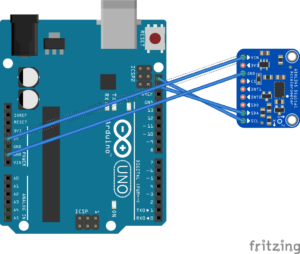
Arduino I2C pins are not internally pulled HIGH. However, the ADXL345 sensor is typically available as a module, where the sensor's I2C pins are already integrated HIGH. Therefore, we can directly connect the I2C pins of the ADXL345 sensor to the I2C port of the Arduino board.
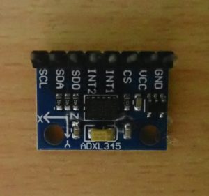
The ADXL345 can receive power from the Arduino's 5V power output. This circuit diagram shows the ADXL345 interface with Arduino.
I2C on Arduino
Most Arduino boards have at least one I2C module, which can be accessed through one or more ports. An Arduino board can serve as an I2C master and slave. To read data from a digital sensor like the ADXL345, however, the Arduino needs to be programmed as an I2C master. It can also be programmed to talk to I2C/TWI devices using the wire library.
- Configure the Arduino as an I2C master by calling Wire.begin with no arguments.
- The Arduino master can set the I2C clock frequency using the Wire.setClock method if the clock speed needs to be modified.
- Arduino can transmit data to a slave (such as ADXL345 to configure settings) by calling the Wire.beginTransmission , Wire.write and Wire.endTransmission methods.
- The Arduino can also request data from a slave using the requestFrom method and retrieve the requested data using the Wire.available and Wire.read methods.
Talking to the ADXL345 using Arduino
Each I2C slave device must have a unique I2C address. The ADXL345 has an ALT address pin that can be connected to set the I2C address of this digital sensor. If the ALT ADDRESS pin is set to HIGH on a module, the 7-bit I2C address for the device will be 0x1D – followed by the R/W bit.
This translates to 0x3A for writing and 0x3B for reading. If the ALT ADDRESS pin is connected to ground, the 7-bit I2C address for the device is 0x53 (followed by the R/W bit). This translates to 0xA6 for writing and 0xA7 for reading.
On a module, the ALT ADDRESS pin is already pulled HIGH or LOW. The I2C address of the ADXL345 sensor used in this tutorial is 0x53. By using this address, Arduino can access the sensor on the I2C bus.
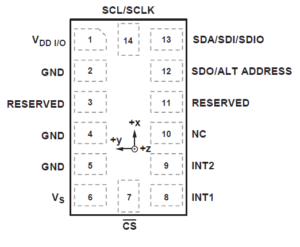
The Arduino needs to read and write data to the ADXL345 registers to configure settings (including setup measurement range, data transfer rate, sensitivity, and resolution) and to read acceleration values.
Here is a table of these records:
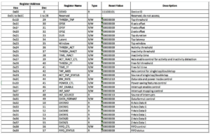
When writing data to the ADXL345, the sensor can be addressed using the Wire.beginTransmission method. The first byte indicating the ADXL345 register (where the data will be written) must be sent followed by the data byte using the Wire.write method. Transmission is completed only when the Wire.endTransmission method is called.
When reading data from the ADXL345, the sensor must be addressed using the Wire.beginTransmission method. The first byte indicating the ADXL345 register (where the data will be read) must be written by the Arduino master on the I2C bus using the Wire.write method.
This transmission is only completed when the Wire.endTransmission method is called. Zero data is sent along with the register address when it needs to be read from the ADXL345 register. And immediately after addressing the register to be read, the Arduino master must make a call to the Wire.requestFrom method to read the value of the selected register.
Configuring the ADXL345 sensor
Below are some simple steps to configure the ADXL345 sensor for serial communication.
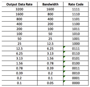
1. Set the power mode and data transfer rate by writing to the 0x2C register. This register has these bits:

If the LOW_POWER bit is set to 0, the ADXL345 operates in normal mode. If set to 1, the ADXL345 operates in reduced power modes where there is increased noise.
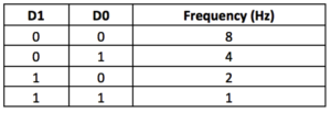
Bits D3 to D0 select the data transfer rate according to this table:
2. Set the data format by writing to register 0x31. It has these bits:

If the SELF-TEST bit is set to 1, a self-test force will be applied to the sensor, causing a change in the output data. If set to 0, self-test strength will be disabled.
If the SPI bit is set to 1, the ADXL345 uses three-wire SPI mode. If it is set to 0, it uses four-wire SPI mode.
If the INT_INVERT bit is set to 0, it sets the interrupts to active HIGH and if it is set to 1, it sets the interrupts to active LOW.
If the FULL_RES bit is set to 1, the sensor outputs a full resolution value (10 bits for +/- 2g; 11 bits for +/- 4g; 12 bits for +/- 8g; 13 bits for +/- 8g; 13 bits for +/- 8g; /- 16g). Otherwise, if it is set to 0, the 10-bit default will be used.
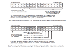
If the justification bit is set to 1, the acceleration values in registers 0x32 to 0x37 are left justified. If set to 0, these values are right-justified.
The following image shows the format of the data value registers with left and right justifications and the positions of the LSB or MSB for different measurement ranges.
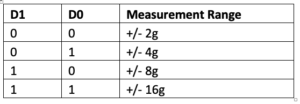
Range bits D1 and D0 select the measurement range according to this table:
3. Set power saving features by writing to register 0x2D, which has these bits:

If the link bit is set to 1, the activity and inactivity functions are serially linked (which means that the activity function will be delayed until the inactivity function is detected). If it is set to 0, both functions will be simultaneous. The idle function refers to a situation where the acceleration is below the THRESH_INACT value (or the 0x25 register) for at least the time indicated by the TIME_INACT (the 0x26 register).
If the link bit is set and the AUTO_SLEEP bit is set to 1, it enables the auto-sleep functionality. In this mode, the ADXL345 automatically switches to sleep mode if the sleep function is enabled and inactivity is detected. If activity is also enabled, the ADXL345 automatically wakes up from sleep after detecting it and returns to operation at the output data rate set in the BW_RATE register.
If the AUTO_SLEEP bit is set to 0, it disables automatic switching to sleep mode. If the link bit is not set, the AUTO_SLEEP feature is disabled and setting the AUTO_SLEEP bit will have no impact on device operation.
If the Measure bit is set to 1, the ADXL345 operates in measurement mode. If set to 0, the ADXL345 operates in standby mode.
If the Sleep bit is set to 1, the ADXL345 will operate in sleep mode. If set to 0, the ADXL345 operates in normal mode. Sleep mode suppresses DATA_READY, stops data transmission to FIFO, and changes the sample rate to that specified by the enable bits.
In sleep mode, only the activity function can be used. The enable bits control the read frequency in sleep mode according to this table:
Reading ADXL345 Acceleration
The acceleration over:
- The X axis is read from registers 0x32 and 0x33
- The Y axis is read from registers 0x34 and 0x35
- The Z axis is read from registers 0x36 and 0x37
The raw values are 16 bits divided into two to complete the form. The resolution, left/right justification of values and measuring range are defined according to the value recorded in register 0x31 of the ADXL345.
In any measurement range, 10-bit resolution can be selected. The 10-bit acceleration value can be adjusted left or right. If the value is adjusted to the right, 10-bit acceleration values can be obtained by masking the second byte (which is read from 0x33 for the x-axis, 0x35 for the y-axis, and 0x37 for the z-axis) — with 0x03, shifting it o to the right eight times. Then the two bytes are combined (0x32 and 0x33; 0x34 and 0x35; 0x36 and 0x37) into a 16-bit integer.
If the value is adjusted to the left, 10-bit acceleration values can be obtained by shifting the first byte to the right (which is read from 0x32 for the x-axis, 0x34 for the y-axis and 0x36 for the z-axis) six times , masking the second byte (which is read from 0x33 for the x-axis, 0x35 for the y-axis and 0x37 for the z-axis) with 0x3F for a temporary byte. Its temp byte is shifted left twice, adding the temp byte to the first byte. Then shift the first byte to the left six times and combine the two bytes (0x32 and 0x33; 0x34 and 0x35; 0x36; and 0x37) to get a 16-bit integer.
This 10-bit value will range from 0 to 1024. Acceleration is measured in both directions along the axis. Therefore, if the value is greater than 511, subtract 1024 from it to get a negative value that indicates the other direction of the axis.
For 10-bit resolution, the acceleration value in one unit of gravity can be derived by multiplying this value by 4 mg (0.004) for +/- 2g range, 7.8 mg (0.0078) for +/ - 4g, 15.6 mg (0.0156) for +/- 8g or 31.25 mg (0.03125) for +/- 16g.
If the selected resolution is 11-bit for the +/- 4g range and the acceleration values are set correctly, 11-bit acceleration values can be obtained by masking the second byte (read from 0x33 for the x-axis, 0x35 for the y axis and 0x37 to z axis) – with 0x07, shifting it to the right eight times and combining the two bytes (0x32 and 0x33; 0x34 and 0x35; 0x36; and 0x37) to a 16-bit integer.
If the selected resolution is 11-bit for the range +/- 4g and the acceleration values are set to the left, 11-bit acceleration values can be obtained by shifting the first byte to the right (read from 0x32 for the axis x, 0x34 for the y-axis, and 0x36 for the z-axis) five times, masking the second byte (read from 0x33 for the x-axis, 0x35 for the y-axis, and 0x37 for the z-axis) with 0x1F for a temporary byte. Then shift the temporary byte to the left three times, add the temporary byte to the second byte, shift the second byte to the left five times, and finally combine the two bytes (0x32 and 0x33; 0x34 and 0x35; 0x36; and 0x37) to a 16-bit integer.
This 11-bit value will range from 0 to 2048. Acceleration is measured in both directions along the axis. Therefore, if the value is greater than 1023, subtract 2048 from it to get a negative value, which indicates the other direction of the axis.
For 11-bit resolution for the range +/- 4g, the acceleration value in the unit of gravity can be derived by multiplying this value by 3.9 mg (0.0039).
If the selected resolution is 12-bit for the +/- 8g range and the acceleration values are set correctly, 12-bit acceleration values can be obtained by masking the second byte (read from 0x33 for the x-axis, 0x35 for the y axis and 0x37 to the z axis) – with 0x0F, shifting it to the right eight times and combining the two bytes (0x32 and 0x33; 0x34 and 0x35; 0x36; and 0x37) to a 16-bit integer.
If the selected resolution is 12-bit for the range +/- 8g and the acceleration values are set to the left, 12-bit acceleration values can be obtained by shifting the first byte to the right (read from 0x32 for the axis x, 0x34 for the y-axis, and 0x36 for the z-axis) four times, masking the second byte (read from 0x33 for the x-axis, 0x35 for the y-axis, and 0x37 for the z-axis) with 0x0F for a temporary byte. Then shift the temporary byte to the left four times, add a temporary byte to the first byte, shift the second byte to the left four times, and combine the two bytes (0x32 and 0x33; 0x34 and 0x35; 0x36; and 0x37) to get a 16-bit integer.
This 12-bit value will range from 0 to 4096. Acceleration is measured in both directions along the axis. Therefore, if the value is greater than 2047, subtract 4096 from it to get a negative value, which indicates the other direction of the axis.
For 12-bit resolution for the +/- 8g range, the acceleration value in the unit of gravity can be derived by multiplying this value by 3.9 mg (0.0039).
If the selected resolution is 13-bit for the +/- 16g range and the acceleration values are set correctly, 13-bit acceleration values can be obtained by masking the second byte (read from 0x33 for the x-axis, 0x35 for the y axis and 0x37 to z axis) – with 0x1F, shifting it to the right eight times and combining the two bytes (0x32 and 0x33; 0x34 and 0x35; 0x36; and 0x37) to a 16-bit integer.
If the selected resolution is 13-bit for the range +/- 16g and the acceleration values are set to the left, 13-bit acceleration values can be obtained by shifting the first byte to the right (read from 0x32 for the axis x, 0x34 for the y-axis and 0x36 for the z-axis) three times, masking the second byte (read from 0x33 for the x-axis, 0x35 for the y-axis and 0x37 for the z-axis) – with 0x03 for a temporary byte, shift the temporary byte to the left five times, add a temporary byte to the first byte, shift the second byte to the left three times, and combine the two bytes (0x32 and 0x33; 0x34 and 0x35; 0x36; and 0x37) to a 16-bit Integer .
This 13-bit value will range from 0 to 8192. Acceleration is measured in both directions along an axis. Therefore, if the value is greater than 4,095, subtract 8,192 from it to get a negative value, which indicates the other direction of the axis.
For 12-bit resolution for the +/- 16g range, the acceleration value in the unit of gravity can be derived by multiplying this value by 3.9 mg (0.0039).
Detecting tilt of the ADXL345
The acceleration value obtained in gravity units can vary from +2 g to -2g, or +4g to -4g, or +8g to -8g, or +16g to -16g — depending on the selected measurement range.
The acceleration value includes both static acceleration due to gravity and dynamic acceleration due to motion or shock.
This image shows the acceleration values in gravity units due to gravity:
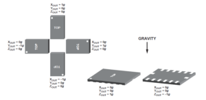
The tilt of the sensor can be detected by the sign and value of the acceleration in the x, y and z axes. When only static acceleration is acting on the ADXL345 sensor, the value of the acceleration along a given axis will be approximately +1g or -1g.
By examining the acceleration signal and value in all axes, the exact orientation of the ADXL345 sensor in a three-axis frame can be determined. How the sensor orientation is expressed (such as the degree tangent to the axial planes) and how the orientation is used for some electronic control application (such as to point the device or control the three-dimensional movement of a system) depends on the user program .
Configuring the ADXL345 for +/- 2g, 10-bit resolution and read acceleration using Arduino
The following Arduino sketch configures the ADXL345 sensor for a measurement range of +/- 2g and uses a 10-bit resolution. The script reads the acceleration data for each of the axes and converts it into gravity units.
Acceleration values on the x, y and z axes are 10 bits and right justified. Consequently, values are derived from 16-bit registers. In 10-bit resolution, the acceleration value in the unit of gravity is obtained by multiplying by 4 mg, that is, by multiplying by 0.004.
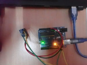
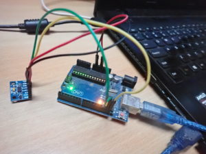
Results
The value of the acceleration along different axes in relation to the different orientations of the ADXL345 sensor can be seen in this video:
In the next tutorial, we will learn how to use the SPI interface on Arduino.
(tagsToTranslate)Arduino

