There are many models of wirelessly controlled robotic vehicles. Typically such robots are connected to a remote control via RF module, Bluetooth, Wi-Fi or cell phones. All of these wireless technologies have their own limitations and are restricted to specific ranges. As if the robotic vehicle is connected to the remote control via Bluetooth module (such as HC-05 Bluetooth module), it can have a maximum operating range of up to 10 meters. If the robotic vehicle is connected to the remote control via RF module, it can have maximum operational range up to a distance of 50 to 60 meters. In this project, an internet-controlled robotic vehicle is designed that will be controlled by a web page. The web page can be opened on any desktop, laptop or mobile phone. The robotic vehicle can be anywhere with internet access and can be controlled remotely from anywhere.
The robotic vehicle was designed in Particle Photon. To manufacture the vehicle, two DC motors are interconnected to the particle board through the L293D motor driver IC. A DHT-11 temperature and humidity sensor and an LDR sensor are also connected to the board to monitor the physical environment around the robotic car. Particle Photon is an IOT board with built-in Wi-Fi and Bluetooth modules. The board operates over the air by connecting to a Wi-Fi connection. The board automatically connects to Particle's Cloud service and can be controlled over the internet by sending data through the company's cloud service.
Particle Photon is an Arduino compatible IOT board. To write program code for any Photon, the developer needs to create an account on the Particle website and register the Photon board with his user account. The program code can then be written in the Web IDE on the Particle website and transferred to a registered IOT board over the Internet. If the selected particle panel, Photon here, is turned on and connected to the Particle cloud service, the code is written to the selected panel over the air via an internet connection and the panel starts operating according to the transferred code.
To control the board over the internet, a web page was developed that uses Ajax and JQuery to send data to the board using the HTTP POST method. The page identifies the board by a device ID and connects to Particle's Cloud Service via an access token.
Required components –
Receiver side:
1. Photon Particle.
2. DHT11 sensor.
3. LDR sensor.
4. Home Wi-Fi connection.
5. L293D Motor Driver IC
9. DC Motors
Transmitter side:
1. Web Page (EngineersGarageIoT.html)
Block diagram –
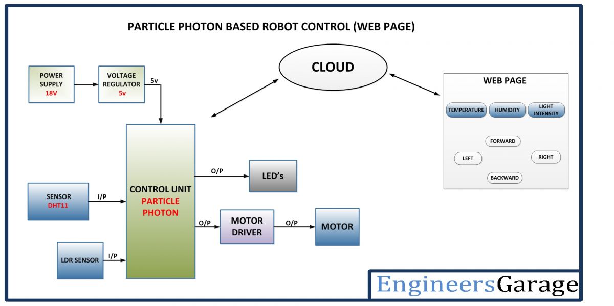
Figure 1: Block diagram of an Internet-controlled robot car based on particle photons
Circuit Connections –
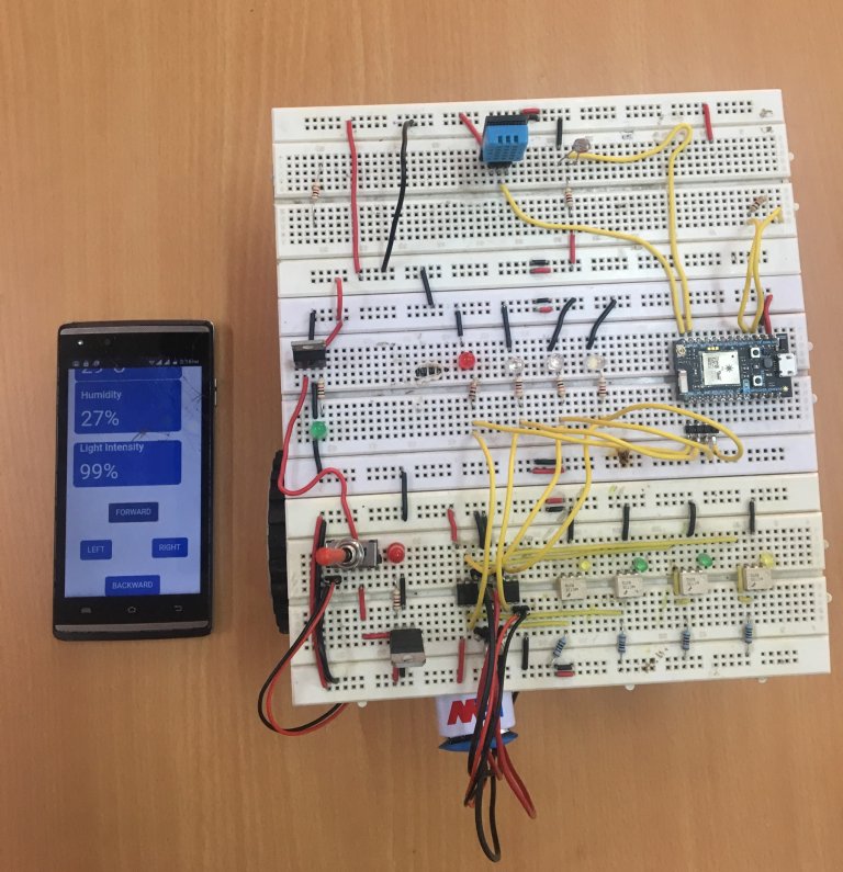
Fig. 2: Internet-controlled robot car prototype based on particle photons
The motor driver IC and sensors interface with the Particle Photon. The circuit is assembled as follows –
Power supply – In the circuit, Photon and other ICs need a regulated DC of 5V for their functioning. An 18V battery is used as the primary power source. The battery power is regulated to 5V and 12V using 7805 and 7812 ICs. Pin 1 of both voltage regulator ICs is connected to the battery anode and pin 2 of both ICs is connected to ground. The respective voltage outputs are taken from pin 3 of the respective voltage regulator ICs. An LED along with a 10K Ω pull-up resistor is also connected between the common ground and the output pin to get a visual cue of power continuity.
DHT-11 Temperature and Humidity Sensor – The DHT-11 sensor reads the ambient temperature and humidity and relays the data to the microcontroller as digital data. The data pin of the DHT11 temperature and humidity sensor is connected to the A0 pin of the Particle Photon, and the VCC and ground are connected to the common VCC and ground.
LDR sensor – The LDR is used to detect light intensity. The sensor is connected to Particle Photon pin A1. The sensor is connected to a potential divider circuit. The LDR provides an analog voltage that is converted to a digital readout by the integrated ADC.
L293D DC Motor Driver IC – The L293D is the motor control driver IC. It has 16 pins with the following pin configuration:
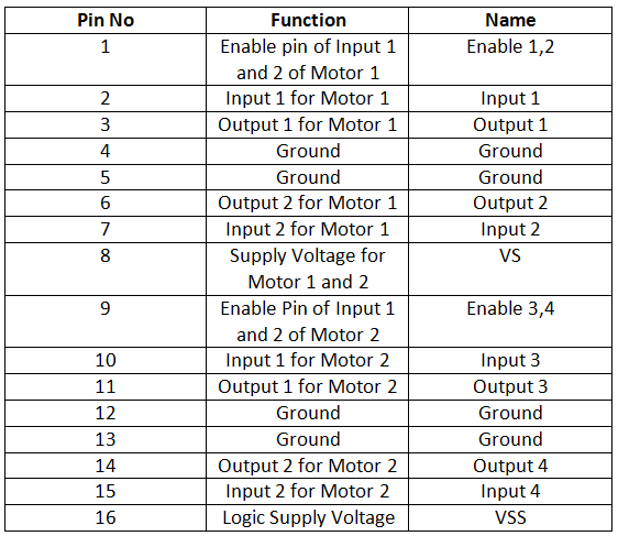
Fig. 3: Table listing the pin configuration of the L293D motor driver IC
There are two DC motors used to make the robotic car. DC motors interface between pins 3 and 6 and pins 14 and 11 of the motor driver IC.
IC L293D controls DC motors according to the following truth tables:
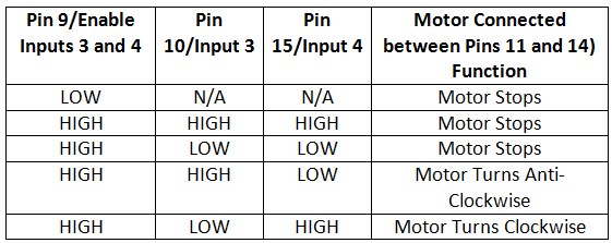
Fig. 4: Truth table of L293D motor driver IC
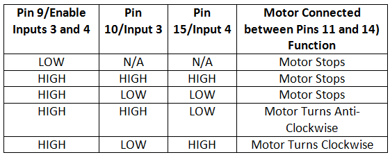
Fig. 5: Truth table of L293D motor driver IC
Pins 4, 5, 13 and 12 of the L293D are grounded while pins 1, 16 and 9 are connected to 5 VDC and pin 8 is connected to 9 VDC. Pins 15, 2, 7 and 10 of the motor driver IC are connected to pins D3, D2, D1 and D0 of the Particle Photon.
How the circuit works –
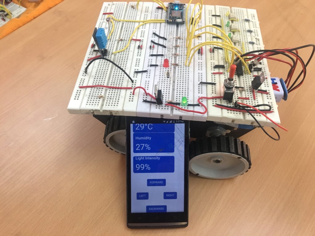
Fig. 6: Image of an Internet-controlled robot car based on photon particles
Once the program code is transferred to Particle Photon, it starts operating accordingly. The Particle Photon must be connected to any internet hotspot via Wi-Fi. The Arduino compatible code in the Photon initially sends a logic LOW on all data pins, pausing both motors and begins fetching data from the sensors.
The DHT11 Temperature and Humidity Sensor is a digital sensor with a built-in capacitive humidity sensor and thermistor. It transmits a real-time temperature and humidity reading every 2 seconds. The sensor operates with a power supply of 3.5 to 5.5 V and can read temperatures between 0° C and 50° C and relative humidity between 20% and 95%. The DHT 11 Sensor sends data in digital format to a controller pin in the one-wire protocol that must be implemented on the firmware side. First, the data pin is configured for input and a start signal is sent to it.
The start signal comprises a LOW for 18 milliseconds followed by a HIGH for 20 to 40 microseconds followed by a LOW again for 80 microseconds and a HIGH for 80 microseconds. After sending the start signal, the pin is configured for digital output and the 40-bit data consisting of temperature and humidity reading is locked. Of the 5-byte data, the first two bytes are the integer and decimal part of the relative humidity reading respectively, the third and fourth bytes are the integer and decimal part of the temperature reading, and the last is the checksum byte . The one-wire protocol is implemented in the firmware using an open source library available for Photon.
The IR sensor outputs an analog voltage at the pin of the interfaced controller. Analog voltage is read and digitized using the integrated ADC channel. The analogRead function is used to read the analog voltage at the controller pin.
The data read from the sensor is passed to the Particle Cloud via Wi-Fi connection and the board waits for the command to move the vehicle. The user sees the sensor data on the web page and has buttons to move and turn the car on the same web page. As the user taps a button, the command in string form is transferred over the internet via Particle's Cloud service. Strings are received via the HTTP POST method by Particle Photon. Upon detecting the command, the board changes the digital logic on the data pins by rotating the motors clockwise or counterclockwise.
In the robot circuit, considering two-wheel drive, whether front or rear, the right side motor (RHS) is connected between pins 3 and 6 and the left side motor (LHS) is connected between pins 11 and 14 from L293D. The RHS motor is controlled by pins 2 and 7 of the L293D while the LHS motor is controlled by pins 10 and 15 of the L293D. Therefore, to move the robot in different directions, the following digital outputs on the L293D pins are required:
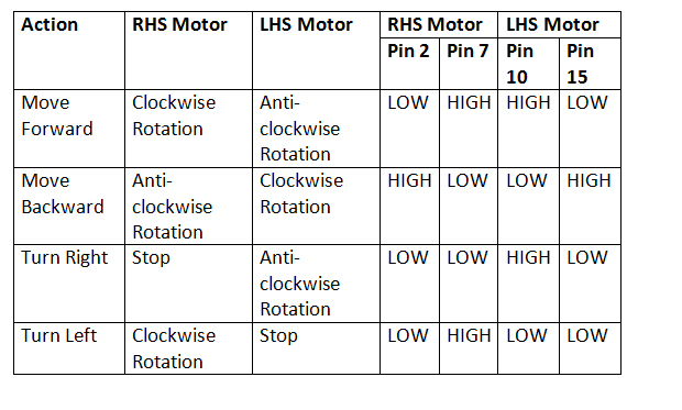
Fig. 7: L293D Motor Driver IC Logic Table for IoT Photon Based Robotic Car
Therefore, to propel the robot in this two-wheel drive, the RHS motor needs to be rotated clockwise and the LHS motor needs to be rotated counterclockwise. This is done by passing LOW signals to pins 2 and 15 of the L293D and HIGH signals to pins 7 and 10 of the L293D according to the truth table. To drive the robot backwards (applicable to two-wheel drive), the RHS motor needs to be rotated counterclockwise and the LHS motor needs to be rotated clockwise. This is done by passing LOW signals to pins 7 and 10 of the L293D and HIGH signals to pins 2 and 15 of the L293D according to the truth table.
To turn the robot to the right, the RHS motor must be stopped and the LHS motor must be turned counterclockwise. This is done by passing LOW signals to pins 2, 7 and 15 of the L293D and HIGH signals to pin 10 of the L293D according to the truth table. To turn the robot to the left, the LHS motor must be stopped and the RHS motor must be turned clockwise. This is done by passing LOW signals to pins 2, 10 and 15 of the L293D and HIGH signals to pin 7 of the L293D according to the truth table. The motors are stopped in the design by providing both L293D control inputs for each motor with LOW logic.
Check out the Photon code to learn how the Arduino-compatible code detects commands in the air and reads data from sensors and publishes it to the linked data logging URL. Learn how the command string is manipulated to change the digital logic on the pins connected to the L293D motor driver IC.
Programming guide –
Photon code
First of all, the DHT sensor library is imported. The library is automatically added by the Particle Web IDE. A constant is defined to denote the pin to which the DHT sensor 11 is connected and a constant is defined to denote the variant of the DHT sensor. Variables to contain temperature, humidity and light intensity values are declared. Variables denoting the motor control logic are declared and assigned to the microcontroller pins. An object of type DHT is declared.
A character array is declared to contain the sensor data to be sent to the web page.
The setup function is called in which the pins connected to the L293D are declared as output pins using the pinMode function and set to LOW by default using the digitalWrite function. The DHT sensor is initialized by calling the begin method on the dht object. A getpos variable and setpos function are exposed from the cloud and retrieved through the POST method by calling the Particle.variable and Particle.function methods. The setup function is executed only once at the beginning of the code.
The loop function is called and iterates infinitely. In the loop function, DHT sensor data is obtained using the getTempCelcius and getHumidity methods on the dht object. LDR sensor data is obtained by calling the analogRead method and converted to light intensity using standard formulas. Data from different sensors are stored in variables, grouped into suitable strings, and sent to the data logging URL using the publish method on the Particle object.
The ledToggle function manipulates the command string. The string is converted to an integer and compared with 1 to 4 to change the logic on the L293D motor input pins.
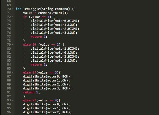
Fig. 8: Screenshot of the Particle Photon Code ledToggle function for the Internet-controlled robotic car
This completes the program code in the Photon for Internet Controlled Robotic Vehicle.
HTML code
To control the robot over the internet, it is necessary to create a web page.
Fig. 9: Screenshot of the source code of the web page that controls the robotic car
The doctype is declared to set the page to the HTML 5 version and the head element is added. Inside the head element, the character set is set to utf-8 and the web page is set to span the entire window. Bootstrap for CSS and Javascript is included in the CDN using the link element.
The body element is declared and an additional splitter element is declared to contain the content of the web page. The web page is structured through other dividing elements and some header paragraph elements and buttons are added.
Javascript is incorporated in which the device ID and access token are declared as variables and a switchLED function is created to format the command string to be passed to the particle board. The command string contains a number between 1 and 4. Page elements are accessed via the getElementbyID JavaScript function. Sensor data is obtained using the JSON.parse method and embedded into HTML elements using the innerHTML method. The $.Post method is used to retrieve data from the cloud using the HTTP POST method.
This is an HTML file that needs to be executed to send data to Particle's Cloud service. The cloud service automatically connects to Photon and Code on Photon operates based on the data received from the cloud.
Project source code
###
//Program to // This #include statement was automatically added by the Particle IDE. #include//DHTparameters #define DHTPIN A0 #define DHTTYPE DHT11 //Variables int temperature; int humidity; int light; int light_sensor_pin = A1; int uv = A3; int pos = 0; intvalue; // Pins int motor0 = D0; int motor1 = D1; int motor2 = D2; int motor3 = D3; // DHT sensor DHT dht(DHTPIN, DHTTYPE); // publishjson.ino -- Spark Publishing Example unsigned long lastTime = 0UL; char publishString(64); void setup { Serial1.begin(9600); pinMode(motor0,OUTPUT); pinMode(motor1,OUTPUT); pinMode(motor2,OUTPUT); pinMode(motor3,OUTPUT); digitalWrite(motor0,LOW); digitalWrite(motor1,LOW); digitalWrite(motor2,LOW); digitalWrite(motor3,LOW); dht.begin; // We are also going to declare a Particle.function so that we can turn the LED on and off from the cloud. Particle.function("led",ledToggle); } void loop { // Temperature measurement temperature = dht.getTempCelcius; // Humidity measurement humidity = dht.getHumidity; // Light level measurement float light_measurement = analogRead(light_sensor_pin); light = (int)(light_measurement/4096*100); unsigned long now = millis ; //Every 5 seconds publish uptime if (now-lastTime>5000UL) { lastTime = now; sprintf(publishString,"{"Temperature": %u, "Humidity": %u, "Light": %u}",temperature,humidity,light); Particle.publish("Uptime",publishString); digitalWrite(motor0,LOW); digitalWrite(motor1,LOW); digitalWrite(motor2,LOW); digitalWrite(motor3,LOW); } } int ledToggle(String command) { value = command.toInt; if (value == 1) { digitalWrite(motor0,HIGH); digitalWrite(motor1,LOW); digitalWrite(engine2,HIGH); digitalWrite(motor3,LOW); return 1; } else if (value == 2) { digitalWrite(engine1,HIGH); digitalWrite(motor0,LOW); digitalWrite(engine3,HIGH); digitalWrite(motor2,LOW); return 1; } else if(value == 3){ digitalWrite(engine0,HIGH); digitalWrite(motor1,LOW); digitalWrite(motor2,LOW); digitalWrite(engine3,HIGH); return 1; } else if(value == 4){ digitalWrite(motor0,LOW); digitalWrite(motor1,LOW); digitalWrite(engine2,HIGH); digitalWrite(motor3,LOW); return 1; } else { digitalWrite(motor0,LOW); digitalWrite(motor1,LOW); digitalWrite(motor2,LOW); digitalWrite(motor3,LOW); return 0; } } ###
Circuit diagrams
| Internet controlled robot car, circuit diagram, particles, photons | 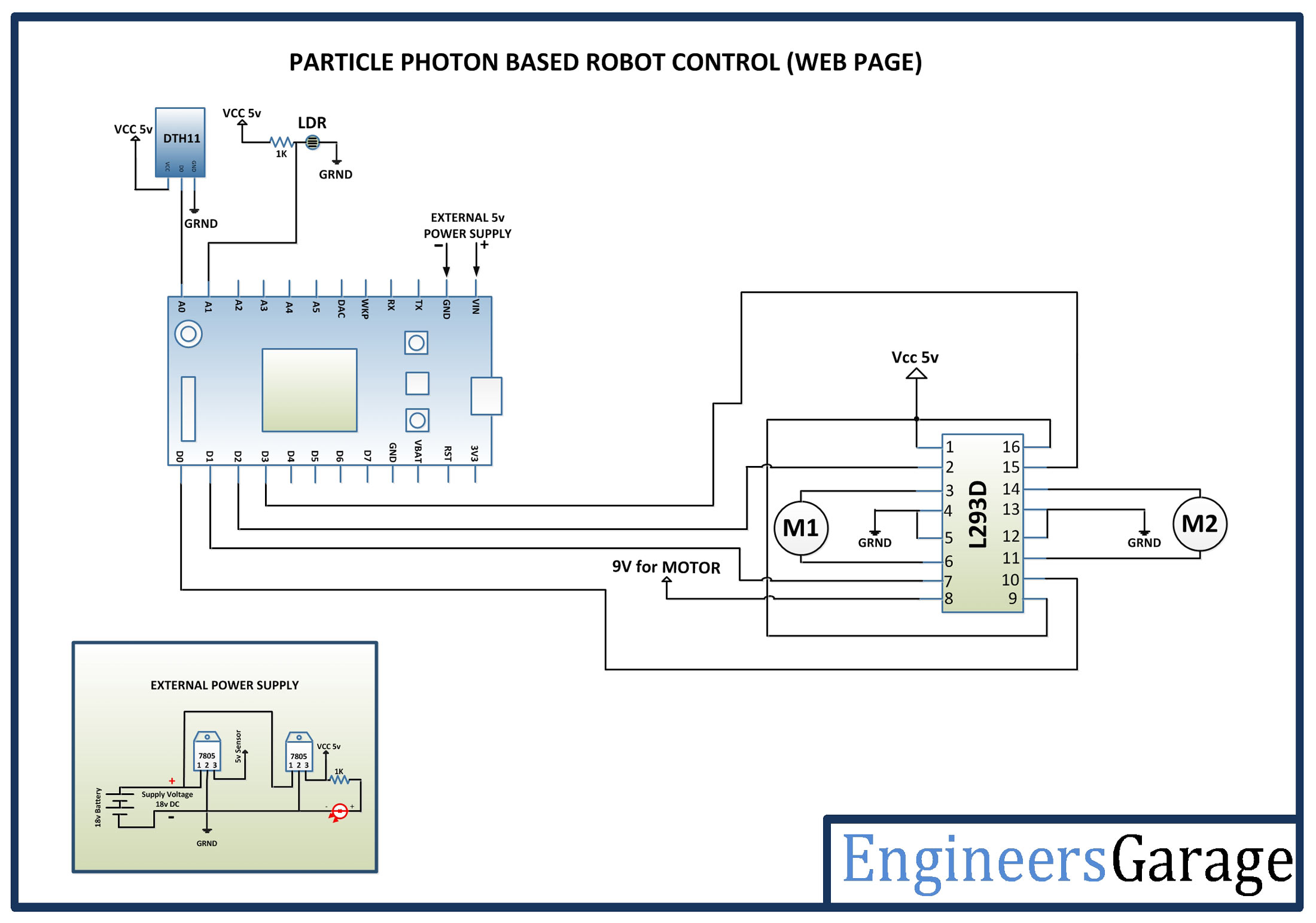 |

